
Frequently Asked Questions (FAQ)
FAQ CATEGORIES
3D Print Questions
Why my 3D printer head (PH40) goes into Stand-By mode while working
The printers are going into standby and eventually shutting off because they are not receiving the correct signal from UCCNC that the machine is running. This is a very simple fix outlined below.
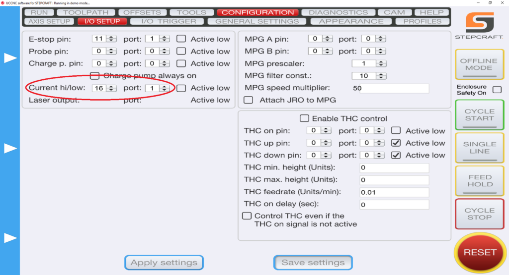
1.) Define pin outs in UCCNC –> CONFIGURATION –> I/O SETUP. On the left hand side you have “Current hi/low”. Those two pins should read “16” and “1”.
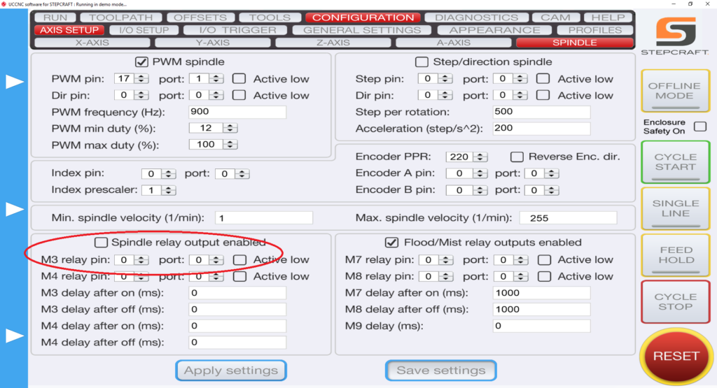
2.) Define pin outs in UCCNC –> AXIS SETUP –> SPINDLE. Bottom Left you have “M3 relay pin”. Change those values to “0” and “0” and uncheck the “spindle relay output enabled” if it is checked.
What software is needed if I purchase the 3D Printer attachment?
You do not need any additional software. The 3D Printer attachment comes with Repetier Host slicing software to create the GCode for the the 3D print files. That file is then run in UCCNC which comes with the STEPCRAFT CNC machine.
What is the maximum project height I can 3D print?
The maximum print height is as follows:
STEPCRAFT 420, 600 and 840 – 120mm (4.72″)
STEPCRAFT 300 – 92mm (3.62″)
If you are using the STEPCRAFT Heated Bed, then you need to subtract 17mm (.67″) from the total print height.
What are the Parameters for the Stepcraft PH-40 Printing Head in Cura?
Cura does not come with the Stepcraft PH-40 as a pre-configured printer, and thus requires creating a custom printer profile (please see the PH-40 First Steps UCCNC manual for more information). Below is a PDF containing the parameters for your Cura profile. Please note that the nozzle diameter setting is dependent on what size nozzle is fitted to the print head.
Stepcraft PH-40 Cura Printer Settings
How Do I Level My Heated Bed for the 3D Printer?
The following video will show you how to level your heated bed for your 3D printer…
Does the Laser DL445 use the same port on the STEPCRAFT as the 3D Printer and HF500 spindle?
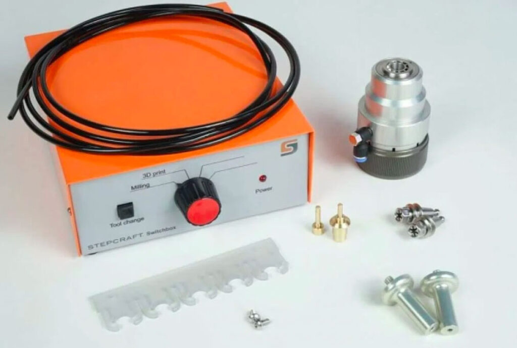
Yes, they both use the same serial port on the back of the machine. You would need to disconnect the cable and reconnect the attachment that you wish to use. STEPCRAFT also offers a Switchbox which allows you to connect everything and simply turn the dial to select the attachment you wish to use. This is very handy if you are constantly changing attachments.

Does the 3D Printer come with filament?
No, it does not. We suggest that you purchase filament from www.matterhackers.com. You will need standard 1.75mm filament.
We can run any PLA, ABS, Custom PLA (flexible, conductive, wood, brass, etc) as well as HIPS
Does the 3D Printer attachment fit all size machines?
Yes, it will work with all Version 1 and Version 2 STEPCRAFT CNC machines.
Do I need to buy additional software if I am only buying the Machine and 3D Printer attachment?
No, since UCCNC is included with the machine to run the G Code and the 3D Printer attachment comes with Repetier-Host slicing software. Those two programs are all you need if you are just going to use your STEPCRAFT CNC for 3D printing. If you are going to use the machine for cutting (spindle, laser, drag knife, etc.) then you need to have a CAM software program as well.
Can I use a 3D scanner to create 3D models to carve as well as 3D print?
Yes, models created with a 3D Scanner are typically saved in common 3D formats like a .stl. These files can be imported into CAM programs like Vectric Cut 3D, Vectric V Carve and Deskproto where they can be assigned tool paths to carve the object out of a material. This is commonly done with two tool paths: Roughing and Finishing, using a standard end mill and a ball nose end mill, respectively.
These files created from a 3D scanner can also be used for a 3D printer.
Here is a good article with a list of the best 3D scanners for 2017: https://pinshape.com/blog/the-11-best-3d-scanners-on-the-market/
STEPCRAFT also has a 3D Touch Probe which can be used for 3D scanning. The following videos show how that works:
Can I connect my HF-500/MM-1000 spindle and 3D printer to the STEPCRAFT at the same time?
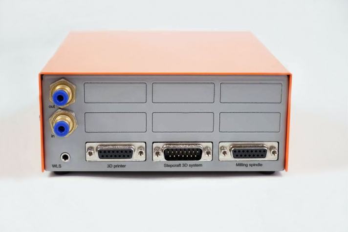
Yes you can with the use of the of the STEPCRAFT System Attachment Switch Box. To use the Switch Box, you simply plug a serial cable from the Switch Box to the serial port on the CNC and then you plug the 3D Printer and the HF500 Spindle into the respective ports on the back of the box. Then you can just rotate the dial to select the attachment that you would like to use and mount that attachment into the tool holder on the STEPCRAFT.
Are there any specific 3D Scanners that work best with STEPCRAFT, or any other CNC?
Honestly, No. Most 3D scanners are capable of generating and saving files in common 3D file format. That is really all that is required for STEPCRAFT. The resolution will vary, though, from scanner to scanner and typically the more expensive they are, the better the scan resolution:
Here is a good article with a list of the top 11 3D scanners for 2017: https://pinshape.com/blog/the-11-best-3d-scanners-on-the-market/
4th Axis
Why would I need a 4th Axis unit?
A typical CNC machine is a 3 axis system, meaning that the tool will move left to right, front to back and up and down. (XYZ axis) This means that you are limited to using flat stocks such as wood, plastic sheets, metal sheets or blocks, etc. However, sometimes you want to expand the capabilities of your CNC and machine round objects like table legs, or chess pieces. For this you would need to install a 4th axis system on your CNC.
The 4th axis is usually installed along your Y axis (in the front to back direction). When using the 4th axis you zero your gantry so the X axis is set to the center line of the 4th axis system and the X axis will no longer move while the job is being machined. Instead the X axis commands are now being transferred to the A Axis. The A Axis is the rotation of the 4th axis. So as the machine is carving or cutting the stock, The gantry still moves front to back (Y axis) and up and down (Z axis), but now you add in the rotation axis (A Axis) which will rotate the stock as the machine cuts/carves the material.
What software do I need to run the 4th Axis system?
In order to use the 4th Axis, you need to have a CAM program that will support creation of the tool path for the 4th axis. Two possible solutions include:
Vectric VCarve Pro (the Desktop version does not support 4th axis). VCarve Pro has a Gadget that will allow you to take a 2D design and wrap it around a cylinder to create a round object. The following video shows you how:
The other option is to use Deskproto Multi-axis addition. This software will also allow you to create a 4th axis job. An added benefit of this program is that it allows you to take a solid 3D model (stl, obj) and place inside a workpiece and then you can carve that object out. See video below showing a Homer Simpson being cut out of foam.
What is the best way to mount the 4th Axis to my STEPCRAFT CNC?
The most important thing when installing a 4th Axis system to any CNC is to make sure you have the ability to infinitely adjust the distance between the chuck and the tail stock. This is important if you are not sure what size stock you will be using. The only time this is not as critical is if you are running the same length stock all the time for every job, then you can install the 4th Axis in a fixed location.
But assuming that you want maximum adjustability, then you should make sure you have a T-Slot Table. installed on your machine. You will then install the 4th Axis Chuck towards the back of the machine facing the front, along the Y Axis. Then the Tail Stock will be installed in the T-Slot channels towards the front of the machine facing the chuck. This will allow you to infinitely adjust both the chuck and the tail stock to accommodate any length stock within your machine’s specifications.
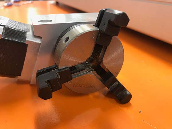
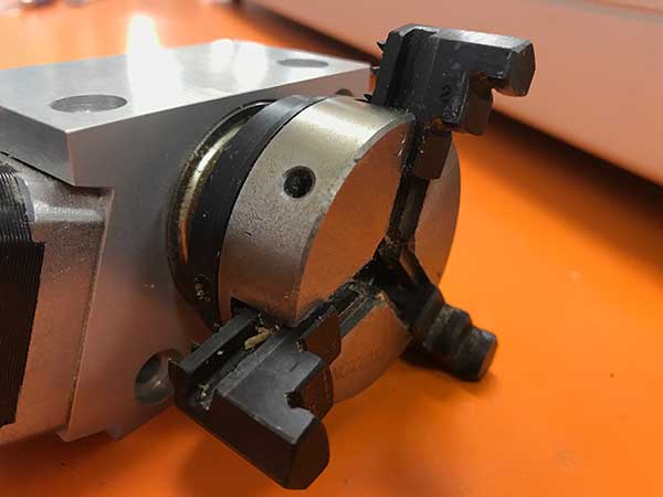
Is the chuck reversible on the 4th Axis unit?
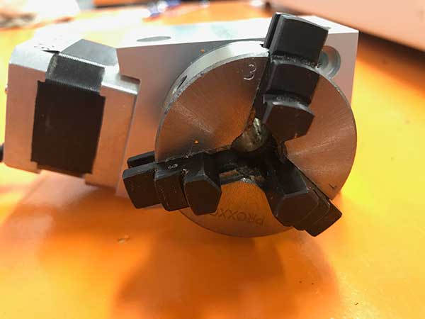
Yes you can remove the three tabs from the chuck and put them in the opposite way to allow for a larger opening for larger stock, up to 2 inches in diameter.
To remove them, simply turn the inner ring behind the chuck counterclockwise and the threads will push the chuck tabs out. Then you can flip them around and while putting pressure on them turn the inner ring clockwise and they will be threaded back in.
If I order a STEPCRAFT CNC Ready To Run with a 4th Axis System, will the 4th Axis be ready to use when I receive it?
The 4th Axis unit requires a board that must be plugged into the main circuit board on the STEPCRAFT. This board will be installed on Ready To Run machines. The only thing you will need to do is to mount the 4th Axis unit and Tail Stock on the T-Slot table and plug the serial cable from the 4th Axis unit into the board.
Note: it is recommended to maximum flexibility for stock size and ease of use that you purchase a T-Slot table for your STEPCRAFT CNC.

Does the 4th Axis Tailstock have a live center (spin with workpiece)?
Yes, the point on the Tail Stock does spin with the work piece. The point rides on a bearing allowing it to freely spin as the workpiece rotates. The Tail Stock is also adjustable so you can move it in and out to secure your workpiece in place without having to use tools.

Are all of the machines capable of using the spindle, laser and 4th axis?
Yes, you can use all of these attachments on each of the machines. However the small size of the STEPCRAFT-1/210 might make it tough to use the 4th axis with longer work pieces. Additionally, the 210 has a limited 3″ Z height, which does not leave a lot of vertical travel and will limit the diameter of material that you can use on the machine. Additionally you really need a T-slot when using the 4th Axis so you can adjust the tail stock for the length of the work material and the 210 is the only machine that does not have a T-Slot option.
Automatic Tool Changer
Where can I find the M31 Macro for the Tool Length Sensor?
The M31 Macro for the Tool Length Sensor is automatically installed when you use the STEPCRAFT Multi-Installer. The best way to make sure you are up to date with our latest profiles and macros is to download the STEPCRAFT Multi-Installer here. This installer will automatically install the most up to date profiles and macros.
If you find that after using the tool length sensor your end mill is slightly above or slightly digs into your material, you may need to preform a small adjustment to the M31 macro. To preform this adjustment, you can find the procedure here.
What shaft diameter end mills can I use on the STEPCRAFT Automatic Tool Changer?
We have SK10 tool holders for 1/8″, 3/16″ and 1/4″ shaft diameters.
You can view them on our webpage: https://stepcraft.us/product/sk10-tool-holder-for-automatic-tool-changer/
What is the collet range sizes that the HF-500 Spindle can accept?
The HF-500 can support up to 8mm ER11 collets. The most popular in North America are 1/8” and 1/4”, but they have collets that range from 1mm to 8mm that will work. The ER11 is an industry standard that determines the overall collet size. ER11, ER16, ER20, ER25 are all common sizes. But the HF 500 and our Tool Changer tool holders for the MM-1000 are both designed for the ER11.

Is there a video on installing and setting up the STEPCRAFT Automatic Tool Changer?
Yes, you can watch a full step-by-step video below.
If I order a STEPCRAFT with an Automatic Tool Changer, will you pre-install the tool rack and setup the software?
Yes we can pre-install the tool rack(s) for you on your machine. We will ALWAYS put them in the rear right corner (when looking from the front of the machine). Additionally, we will setup the tool locations in UCCNC and send you the Macro file that you can simply copy to your installation of UCCNC. Once complete, all locations should be correct and you can start using the ATC right away.
How do you set the tool lengths (Z height) for each tool in the Automatic Tool Changer?
We actually have an automated macro that will do this for you. The video below will explain how to do this.
NOTE: This macro will require the Tool Length Sensor in order for this to work.
How do I connect the cables for the Automatic Tool Changer (ATC) on MM-1000?
How Can I Calibrate My Tool Length Sensor?
If you find that your tool length sensor (TLS) is functioning properly, but not touching the very top of your material, you may need to preform a quick calibration. This ensures that the tool length sensor is accurate and reliable. The following video will walk you through the simple TLS calibration…
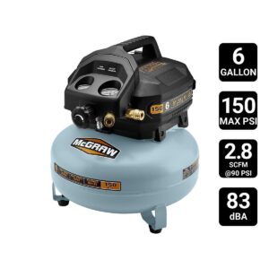
Does the Automatic Tool Changer require an air compressor?
Yes, it will require a small air compressor that is capable of outputting 125-130 PSI of air pressure. We use a small pancake compressor from Harbor Freight that we got for $119.00. They have pricing that ranges and sometimes you can get it for even less money. The direct link to the product is: https://www.harborfreight.com/air-tools-compressors/air-compressors-tanks/air-compressors/6-gallon-08-hp-150-psi-oil-free-pancake-air-compressor-58636.html
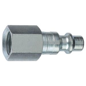
Note: You will need a 1/4 in. FNPT x 1/4 in. I/M Steel Plug fitting to match your compressor’s hose. Here is one from Home Depot: http://www.homedepot.com/p/Husky-1-4-in-FNPT-x-1-4-in-I-M-Steel-Plug-12234HOM/205330359
When you buy an Automatic Tool Changer (ATC), the system might come with an orange switch box. That switch box is intended for use with the ATC on the D.Series line of CNC machines as well as the M.Series machines that DO NOT have a Tool Magazine on the back of the machine. If you did not purchase the optional Tool Magazine then you would need to use the Switch Box. If you have the Tool Magazine, then you DO NOT need to use the switch box.
No, at this time you can not use it because the Exhaust Adapter wraps around the whole spindle, which will interfere with the tool changer putting the tool back into the rack. At this time we do not have plans for a new exhaust adapter design that will be able to be used with the tool changer.
Yes, the tool holders are special collets that you install the end mill into and place it on the tool rack. The tapered design of the top of the tool holder allows it to be grabbed and secured by the tool changer. Tool holders are available in 1/8″, 3/16″ and 1/4″ shaft sizes.
Note: when you buy the Automatic Tool Changer, it comes with two 1/8″ tool holders and a rack that will hold up to 5 tools, so to fill the entire rack, you will need to order 3 more tool holders.
Before You Buy A CNC Router
Why is My UCR201 Jog Pendant Not Showing Up In UCCNC?
The UCR201 Jog Pendant requires the user to enable the plugin in the configuration window in UCCNC. If you are running version 1.2037 of UCCNC, you may find that the Jog Pendant does not show up in the configuration window. If this is the case, you simply need to update UCCNC to a newer version which can be found below…
UCCNC Version 1.2049 – http://www.cncdrive.com/UCCNC/download_UCCNC.php
After downloading and installing version 1.2049 of UCCNC, the Jog Pendant should now be visible in the configuration window and you can proceed with the rest of the setup!
Where can I download UCCNC?
UCCNC is the machine control software that moves your STEPCRAFT machine and interprets G-Code. In order to use your STEPCRAFT machine, you will need the UCCNC software as well as the STEPCRAFT machine specific profiles. You can download and install both from the STEPCRAFT Multi-Installer that comes on your orange USB flash drive, or download here. STEPCRAFT will always have the latest compatible version of UCCNC included in the Multi-Installer. If you are looking for the newest released version of UCCNC, you can download here (note: UCCNC may release versions newer than those included on the STEPCRAFT Multi-Installer. These versions may not have been fully tested and may cause some bugs/issues with your machine. It is reccomended to use the version of UCCNC included on the STEPCRAFT Multi-Installer).
There is really not much comparison between the two. Both tools are similar only in that fact they both hold a router bit and can rotate it to cut material at high speeds. A router is a 110V consumer grade tool that is rated for intermittent use while a spindle is an industrial motor that has been manufactured to run all day long, day in and day out for exactly the purpose you want to purchase it for – CNC cutting. Spindles are more powerful (note that hp ratings between routers and spindles are not comparable) and will maintain their full torque down to much lower RPMs than a router. Spindles have precision bearings, which means less run-out and thus smoother and more accurate cutting. The bearings on a spindle also stand up to continuous use better than those of a router. Bearings in a heavily used router will need to be replaced every three-four months, while a similarly used spindle should be good for a few years between bearing replacements. A spindle is also much quieter in operation than a router.
That been said, if you don’t need a heavy cut and noise is not an issue, then a router is a safe choice. In production situations, we highly recommend a spindle. In addition, the full performance capabilities of our machines are fully realized with a spindle because a router will bog down in heavy cutting at higher cutting speeds.
In making a decision, the real dividing line between the two is on how you make your money. If your paycheck comes from someplace outside your shop, then buy whichever you feel you can afford. If your paycheck is generated inside your shop, and your living and reputation is on the line, you need the security and substantially higher cut quality that comes from a spindle.
Depending on your CNC system, you will need three different software programs.
- CAD/Design
- CAM (Computer Aided Manufacturing)
- Machine Control Software
The CAM software is the one that you will most likely need to purchase in addition to your CNC machine. Some CAM programs like Vectric V Carve or Cut 2D have a design component included in the software, so one program meets both 1 and 2 above.
CAD/Design
Design programs like Adobe Illustrator, Inkscape, Corel Draw. CAD programs like AutoCAD, Fusion 360, Sketchup, Solidworks, etc. STEPCRAFT supports these and many more of the popular CAD/vector design software programs on the market. Depending on what you are looking to do will determine how much knowledge you will need to have on a CAD or design program
CAM
A CAM (computer aided manufacturing) program. A CAM program will take the vectors or 3D model that you have designed and allow you to tell the program which tools you intent to use as well as the material size and the speeds and feed rate that you wish to run for your project. The CAM program will output a G Code file, which is basically common machine language for CNC machines. Vectric programs like V Carve and Cut 2D make this process pretty easy. STEPCRAFT sells and supports the full line of Vectric programs as well as Deskproto Multi-Axis CAM software.
Machine Control
Most CNC machines will come with machine control software. STEPCRAFT, for example, comes with UCCNC when ordered from the USA office. They provide UCCNC as well as WinPC-NC in other parts of the world. Mach 3/4 is a very popular machine control software program which is used with many commercial machines as well as the DIY CNC world. There are also programs line Linux CNC for Linux platforms and come manufacturers will include their own proprietary programs.
You can expect that many commercial CNC machines will come with software, as the machine is useless without it. If you are making your own (DIY) CNC machine, then you will most definitely need to purchase software like UCCNC or Mach 3/4 for machine control.
What is the total usable Z height on the D-Series CNC?
The D-Series 420, 600 and 840 all have a max Z height of 140mm (5.51″). However this does not represent the maximum height of material you can process. From this height you need to subtract the spindle collet nut stick out as well as the length of the cutting tool you are using.
The following represents the spindle and spindle nut stick out you get on a D-Series machine with the HF-500 and MM-1000 spindles
HF-500: 31mm (1.22″)
MM-1000: 38.6mm (1.52″)
MM-1000 (with single spacer): 32.56mm (1.28″)
MM-1000 (with dual spacers): 26.34mm (1.04″)
- NOTE: This is the case with just about every CNC machine on the market, not just STEPCRAFT CNC. Most all CNC machines will have spindle and spindle nut/tool holder stick out that takes away from the usable Z height.
So if you take into consideration the MM-1000 with dual spacers, you would have a total Z height of 140mm (5.51″) minus 26.34mm (1.04″) leaving you with a new max Z height of 113.66mm (4.47″).
Now depending on what you intend to do, you can use this new value to plan your project. If you want to cut all the way through material, you would need to have a tool that is long enough, which you would further subtract from the new Z height value.
Example 1: New Z Value is 113.66mm (4.47″), if you divide that number in half, that would mean you can use a piece of material that is 56.83mm (2.23″) thick and the tool would have to stick out 56.83mm (2.23″) as well.
- NOTE: This would also mean that the cutting height of the tool would have to be a min of 56.83mm (2.23″) or you run the risk of rubbing the shank of the tool on the material.
Example 2: If you intend to only engrave on top of a piece of material, then your tool stick out can be much less. If you use an engraving blank that sticks out say 12mm from the bottom of the collet nut, then that means you can have a max material height of 101.66mm (4″).
- NOTE: please keep in mind you should also allow for a couple 2-3mm of Z height clearance for rapid, non-cutting moves on the CNC as well. So you would subtract another 2-3mm from the above numbers in a practical application.

TWO SIDED MACHINING – For thicker material
One way that you can increase your max material thickness that you can cut through is using double sided machining.
Example: You can take your new Z value of 113.66mm (4.47″) and divide that into thirds. This would mean you can have a material thickness of 75.33mm (2.96″), or two-thirds and using a cutter with a length of 38mm (1.49″) you can cut one side of the project and then flip it over and cut the other side – so you are using a shorter cutter to cut through a thicker material by cutting each side.


Example:
The short answer is that both will work, however, if you are looking for high accuracy then a screw drive system will outperform every time.
Belt-Drive Systems
Belt drive systems are much cheaper to produce and require less expensive components to make them work. A belt drive system is usually a one to one ratio between motor movement and gantry movement. Meaning that there is no gear reduction so as the motor moves, the gantry will move an equal amount. Because of this, the motor on a belt drive system will usually be much larger than a same size lead screw driven system. Belts are also more susceptible to stretching and wear. This will always affect accuracy. If the belt stretches that will immediately translate into an inaccuracy at the bit into your workpiece. Some might argue that a belt drive system will move the gantry faster, but keep in mind that moving faster into a material and having stretch on the belt will cause deflection and the belt will act more like a spring thus increasing the risk for lost steps and positioning.
Screw-Drive Systems
A screw driven system usually consists of a threaded rod (screw) that is either an Acme-type lead screw or a ball screw. The motor will rotate the screw and the gantry is attached to the screw with some type of threaded nut (lead screw nut or ball nut). As the screw turns, the gantry is moved in the corresponding direction. The number of threads per inch will determine how many rotations the screw must turn for the gantry to move one inch. This gear reduction means that you can either use much smaller stepper motors to control the movement and still maintain a very high accuracy, or you can use a larger motor and move a larger mass as compared to using the same size motor in a belt driven system. You will find much better repeatability and accuracy in a screw driven system with minimal to no linear free play. Due to the costs of lead and ball screws and components, you will find that these type of drive systems will cost more than a belt drive system.
Summary
If you are looking for high accuracy, a more rugged design, or if you plan to cut harder materials like hard plastics, hard woods and metals, then you will want a system that uses a screw-drive. If you are just planning to cut thin, softer materials like soft woods and plastics and accuracy is not as important to you, and if you do not have a large budget, then a belt-drive system might be right for you. Always keep in mind when looking at purchasing a CNC system what you might need in the future. You might think that your immediate need to make model parts out of thin plywood, thin plastic and balsa wood might not require a screw drive, but maybe in the future you want to cut hardwoods, thicker plastics or metals, or you get a project that requires a high cutting accuracy – in this case you might be kicking yourself for not spending the extra few hundred dollars for the better drive system.
You can think of the Semi-Closed Loop System as an “electronic insurance policy”. The system uses a special sensor that is installed on each of the 4 CNC motors. This sensor monitors the movement of each motor and compares that movement against what UCCNC is telling it to move.
As an example, if UCCNC wants to move X 35mm to the right and something is interfering with that movement and it only moves 31mm, then the Semi Closed Loop System will immediately stop the system.
The beauty of this system is that you can simply rehome the machine and then continue the job right where you left off. This is especially handy when you are using expensive materials that you do not want to waste.
To be able to make your first CNC project, you need, at minimum, the following items:
- CNC base machine (STEPCRAFT 210, 300, 420, 600 or 840)
- A Spindle (HF500, Kress, Dremel, Dewalt, Proxxon, etc). Please watch this VIDEO for an explanation of all our spindle options.
- Tooling (also know as “end mills”). You will need an end mill for the particular material that you intend to cut/carve. STEPCRAFT sells a Starter Tool Set that comes with an assortment of tools to get you started cutting and carving woods, plastics, aluminum, carbon fiber, composites and two bits are included for engraving.
- CAD/CAM Software. STEPCRAFT includes a free year subscription to Fusion 360, which is a very powerful 3D design and CAM software system. However, Fusion 360, while powerful, is also time consuming to learn and become proficient at. STEPCRAFT also sells Vectric programs (Cut 2D, Cut 3D and V Carve). These programs are better suited for the beginner and will have you up and running with your first projects in a matter of minutes.
NOTE: Having a copy of a Vectric program is a good idea, even if you intend on learning Fusion 360. Vectric programs are quick and easy to setup a job where Fusion will become quick once you learn how to use it. Think of Vectric programs like a sprint and Fusion 360 more like a marathon when it comes to the end result with creating CNC projects.
That’t it! These are the minimum things you need to get started with CNC’ing. You can also check out STEPCRAFT’s Complete System Packages for preconfigured systems that come with everything you need to get started as soon as you receive your new CNC system.
Understanding the Homing Procedure
Whenever you open UCCNC, the very first movement you should make with your machine is “Home All”. On a STEPCRAFT, the homing procedure begins with the Z-Axis, then the X-Axis and finally the Y-Axis. Each axis will run towards its limit switch until it engages the switch, then will run the opposite way until the switch disengages. Once all three axis have hit their limit switch, your machine is now ready to travel the full length of each axis!
This is known as a reference movement for the machine. Without this reference movement, the machine has no idea where it is along its axis and may not travel the full length back and forth. If your machine is stopping short of the full length of travel and you aren’t noticing any binding, make sure to “Home All” and try running again.
One important thing to note is that if any axis ever travels in the opposite direction of its limit switch when homing, check to make sure a limit switch is not engaged somewhere on the machine. All of the limit switches are on the same circuit, so if you tried to home your machine and the Y-Axis limit switch was pressed, the Z-Axis would travel in the OPPOSITE direction. This happens because the machine is going through the stage of homing when it backs away from the switch until it disengages. Because the Y-Axis switch was pressed, the Z-Axis will infinitely try to move away but it will never disengage.
There are three basic software program types that you will need to have some knowledge of when getting ready to use your STEPCRAFT CNC system:
- A design or CAD program. Design programs like Adobe Illustrator, Inkscape, Corel Draw. CAD programs like AutoCAD, Fusion 360, Sketchup, Solidworks, etc. STEPCRAFT supports these and many more of the popular CAD/vector design software programs on the market. Depending on what you are looking to do will determine how much knowledge you will need to have on a CAD or design program
- A CAM (computer aided manufacturing) program. A CAM program will take the vectors or 3D model that you have designed and allow you to tell the program which tools you intent to use as well as the material size and the speeds and feed rate that you wish to run for your project. The CAM program will output a G Code file, which is basically common machine language for CNC machines. Vectric programs like V Carve and Cut 2D make this process pretty easy. STEPCRAFT sells and supports the full line of Vectric programs as well as Deskproto Multi-Axis CAM software.
- UCCNC (or machine control software). This program is used to setup, job and zero the STEPCRAFT CNC as well as loading and running the G Code file that was created from your CAM program.
So answer the question as to how easy it is to learn, really depends on what you are looking to do.
For example, if you are looking to do projects that are pretty complex and require that you design them in Fusion 360 or Illustrator, and you DON’T know how to use these programs, then you will have a longer learning curve since you will have to learn the design program as well.
Assuming that you already know how to use a design or CAD program, then the next program you would need to learn is a CAM program, such as Vectric V Carve. The nice thing about V Carve (or Cut 2D) is that the interface is very easy to learn so you can be on the way of making your first CNC project in a matter of minutes. However, as you progress, these programs have a lot of powerful features that will extend the limits on what you can create on your STEPCRAFT CNC machine.
As for UCCNC, this program takes about 15 minutes to learn how to use. Much of what you see on the screen are buttons and features that you will not use (unless doing advanced features like automatic tool changing, etc). There are only about 5 buttons that you will need to focus on to successfully start creating projects on your STEPCRAFT right away.
This video gives you a basic overview of the software programs and how easy it is to get started right away.
It is comprised of 4 sensors, one mounted on each of the Y-axis motors, one on X and one on Z. The sensors monitor the motors’ movements and compare that movement against what UCCNC (your project’s G-Code file) is telling the motor to move. In the event that one of the motors does not match the intended movement, then the system will immediately go into E-Stop.
As your machine is cutting a project, if it runs into an obstruction, or if there is any other situation that causes the machine to stall in one of the axes, it will stop the system.
To reset, you can simply rehome the machine and then continue running the job from where you left off. You can use the RUN FROM HERE button on UCCNC and the job will continue as if the error never happened. You can watch the following video to learn how to use this feature on UCCNC:
Using a CNC machine is like an artist painting.
The material you are working on is your “canvas” and the bits (otherwise known as “end mills” or “tools”) are the “brushes”
There are literally tens of thousands of bits available for a CNC machine from hundreds of manufacturers. Getting into detail on them all would literally be a book. So for this question we will break it down into XX types:
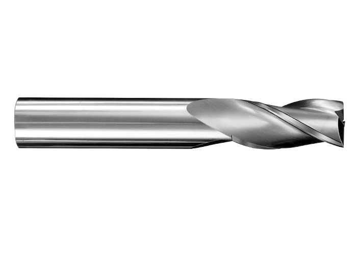
Square nose end mill – These bits are the most common and are what you would likely turn to for all of your CNC cutting. They come in a variety of shapes, sizes and spiral types. If you are just starting out, you might want to have an 1/8″ 2 flute up spiral and a 1/8″ 2 flute down spiral end mill to get you started. Both bits will work in most all CNC machines as an 1/8″ shaft diameter is very popular, even if you are using a Dremel tool as a spindle.
2 Flute is a common type since most CNC routers run at very high RPM, so you need fewer flutes to extract the chips from the material as you are cutting quickly.
Up Spiral bits will pull the chips away from the material, but can leave a frayed top edge of your workpiece, these bits are better for plastics and aluminum and harder woods.
Down Spiral bits will push the chips into the work material but will leave a very clean top edge cut. These bits are best for softer materials and wood as they leave a better finish. They also force the material down into the bed of the machine which is good for thinner materials, where an up spiral bit will tend to pull it away from the bed.
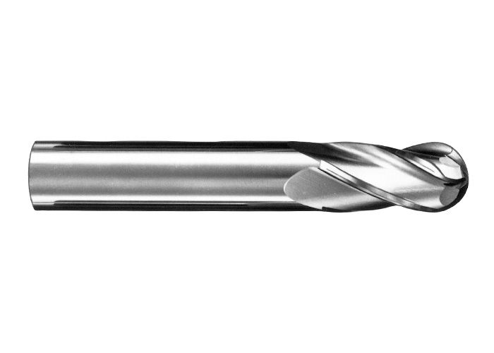
Ball Nose End Mill – These bits have rounded bottom and are typically used for carving 3 dimensional projects. When used properly they can leave a very smooth and detailed finish on your workpiece.
If you are just starting out, I would get a 2 flute 1/8″ and 1/16″ ball nose for your tool kit. These two sizes are very common and depending on the level of detail, you would have a bit for most requirements.
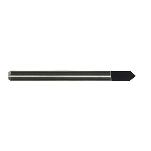
Engraving Bits – These bits will have a V point on the end are used for engraving materials for lettering or designs. Its suggested to have 1/8″ 90 degree and 60 degree engraving bits for your tool kit when you are starting out. These will give you a lot of flexibility for engraving options.
Additionally, if you have a CNC that can support 1/4″ shank bits, then its suggested to get a 1/2″ V router bit with a 1/4″ shank. These are commonly found at home improvement stores like Home Depot and Lowes. This 1/2″ V bit is perfect for sign lettering and when using a program like V Carve, you have the ability to do some really nice 3D lettering.
These are the most common bits that I suggest any beginner have in their tool box. As you gain more experience, you can add many more bits to your system in a variety of shapes and sizes for different applications. STEPCRAFT has a Starter Tool Set
that includes all of these bits which can be found HERE.
This is a question that can be answered in many ways.
Use A Premade Design
The easiest way to get a project made on the CNC is to buy a design that is already done for you. You can find many for free on the internet, but a few VERY good commercial options for 2D and 3D designs are:
- www.makecnc.com – Excellent selection of puzzles and other creative projects.
- www.designandmake.com – Very high quality 3D projects that can be reworked into hundreds of different possibilities.
- www.thingiverse.com – large selection of free 3D designs. Most are for 3D printing but many will work with a CNC as well.
- https://woodgears.ca/gear_cutting/template.html – Gear designer
- http://www.vectric.com/cool-stuff/projects.html – 2D and 3D high quality project files
- www.cnccraze.com – many project files
Bitmap Image Trace
Another option that is no as easy as just buying a file or downloading something that has been already designed, but is still easier than designing something from scratch, is to import an image or logo (i.e. from Google Images) and use the Image Trace feature in Vectric to create a vector from the bitmap image. Once it has been converted into a vector, you can assign tool paths to it and proceed to cut out on your CNC.
Another way to convert your bitmap images to vectors is to use the site (or software) https://vectormagic.com/. The online version of their program works very well and returns a vector that has excellent quality.
The following video shows you how to use Vectric’s Image Trace feature
Design Your Own
Sometimes you can not get exactly what you are looking to create from an online source that is pre-made, so you must turn to making your own design. This is not as scary as it sounds, especially if you are looking to cut out simple things like letters, signs, etc. The CAD (or design) part of Vectric programs make this easy. Cut 2D and V Carve have a design component to their software and you can quickly and easily design many different projects and then switch to the CAM part of the program to create the tool paths and output the G Code to the CNC.
You can also create vector designs with programs like Corel Draw and Adobe Illustrator, or if you need something designed to very specific dimensions, you can use a CAD program like Fusion 360 or Sketchup.
Hire Someone To Design For You
There are many outsourcing websites on the internet where people are looking for design work. You will be find many very talented people from all around the world and many (depending on the country) are willing to work for very reasonable rates.
www.upwork.com is one site where you will be able to post your job and have people bid on the project. You can read up on the applicant, discuss specifics and finally hire the person who best meets your needs.
You can go on websites like www.cnczone.com or the Facebook Group CNC Router Tips and put a post up with what you are looking to have designed and more often than not, you find people who are willing to do your design for a small fee (if not for free)
CNC Manufacturer
If all else fails, then contact the manufacturer of your CNC machine and ask them if they can help with the design or if they know anyone who you could contact.
YouTube is also a good source to find how-to videos that can show you how to make your designs or how to use various software programs.
How do I connect my Remote Switchable Power Controller?
To connect your remote switchable power controller system, follow the diagram below…

When you buy an Automatic Tool Changer (ATC), the system might come with an orange switch box. That switch box is intended for use with the ATC on the D.Series line of CNC machines as well as the M.Series machines that DO NOT have a Tool Magazine on the back of the machine. If you did not purchase the optional Tool Magazine then you would need to use the Switch Box. If you have the Tool Magazine, then you DO NOT need to use the switch box.
Common Pre-Purchase Questions
Will the milling and laser tools work on other metals besides aluminum?
Yes, they will also machine brass and copper. STEPCRAFT machines are only designed for machining of non-ferrous metals. So you can not mill steel, stainless steel, etc.
Also note that the laser will NOT cut metals. you can use it to engrave but it will NOT cut!
Pre-Assemble machines are BUILT TO ORDER. Typical delivery times for a pre-built machine is up to 30 days.
*We typically ship KIT machines within 14 days of purchase.
Why my 3D printer head (PH40) goes into Stand-By mode while working
The printers are going into standby and eventually shutting off because they are not receiving the correct signal from UCCNC that the machine is running. This is a very simple fix outlined below.
1.) Define pin outs in UCCNC –> CONFIGURATION –> I/O SETUP. On the left hand side you have “Current hi/low”. Those two pins should read “16” and “1”.
2.) Define pin outs in UCCNC –> AXIS SETUP –> SPINDLE. Bottom Left you have “M3 relay pin”. Change those values to “0” and “0” and uncheck the “spindle relay output enabled” if it is checked.
Where can I purchase STEPCRAFT in Canada, USA or Mexico?
All sales, service and support is handled for Canada, USA and Mexico out of our offices in Torrington, CT. You can visit www.stepcraft.us for pricing and information. Or you can email info@stepcraft.us.
If you live outside the USA, Canada or Mexico, please visit www.stepcraft-systems.com for a complete list of dealers around the world.
Where can I download UCCNC?
UCCNC is the machine control software that moves your STEPCRAFT machine and interprets G-Code. In order to use your STEPCRAFT machine, you will need the UCCNC software as well as the STEPCRAFT machine specific profiles. You can download and install both from the STEPCRAFT Multi-Installer that comes on your orange USB flash drive, or download here. STEPCRAFT will always have the latest compatible version of UCCNC included in the Multi-Installer. If you are looking for the newest released version of UCCNC, you can download here (note: UCCNC may release versions newer than those included on the STEPCRAFT Multi-Installer. These versions may not have been fully tested and may cause some bugs/issues with your machine. It is reccomended to use the version of UCCNC included on the STEPCRAFT Multi-Installer).
Please visit www.stepcraft-systems.com for a complete list of dealers around the world.
They are manufactured in Menden Germany. If you would like to take a virtual tour of the factory, click www.stepcraft.us/menden.
There is really not much comparison between the two. Both tools are similar only in that fact they both hold a router bit and can rotate it to cut material at high speeds. A router is a 110V consumer grade tool that is rated for intermittent use while a spindle is an industrial motor that has been manufactured to run all day long, day in and day out for exactly the purpose you want to purchase it for – CNC cutting. Spindles are more powerful (note that hp ratings between routers and spindles are not comparable) and will maintain their full torque down to much lower RPMs than a router. Spindles have precision bearings, which means less run-out and thus smoother and more accurate cutting. The bearings on a spindle also stand up to continuous use better than those of a router. Bearings in a heavily used router will need to be replaced every three-four months, while a similarly used spindle should be good for a few years between bearing replacements. A spindle is also much quieter in operation than a router.
That been said, if you don’t need a heavy cut and noise is not an issue, then a router is a safe choice. In production situations, we highly recommend a spindle. In addition, the full performance capabilities of our machines are fully realized with a spindle because a router will bog down in heavy cutting at higher cutting speeds.
In making a decision, the real dividing line between the two is on how you make your money. If your paycheck comes from someplace outside your shop, then buy whichever you feel you can afford. If your paycheck is generated inside your shop, and your living and reputation is on the line, you need the security and substantially higher cut quality that comes from a spindle.
What type of warranty does STEPCRAFT offer?
STEPCRAFT offers a full two-year warranty on all STEPCRAFT brand products and accessories.
The full outline of what is covered is available on the following link: https://stepcraft.us/warranty/
Depending on your CNC system, you will need three different software programs.
- CAD/Design
- CAM (Computer Aided Manufacturing)
- Machine Control Software
The CAM software is the one that you will most likely need to purchase in addition to your CNC machine. Some CAM programs like Vectric V Carve or Cut 2D have a design component included in the software, so one program meets both 1 and 2 above.
CAD/Design
Design programs like Adobe Illustrator, Inkscape, Corel Draw. CAD programs like AutoCAD, Fusion 360, Sketchup, Solidworks, etc. STEPCRAFT supports these and many more of the popular CAD/vector design software programs on the market. Depending on what you are looking to do will determine how much knowledge you will need to have on a CAD or design program
CAM
A CAM (computer aided manufacturing) program. A CAM program will take the vectors or 3D model that you have designed and allow you to tell the program which tools you intent to use as well as the material size and the speeds and feed rate that you wish to run for your project. The CAM program will output a G Code file, which is basically common machine language for CNC machines. Vectric programs like V Carve and Cut 2D make this process pretty easy. STEPCRAFT sells and supports the full line of Vectric programs as well as Deskproto Multi-Axis CAM software.
Machine Control
Most CNC machines will come with machine control software. STEPCRAFT, for example, comes with UCCNC when ordered from the USA office. They provide UCCNC as well as WinPC-NC in other parts of the world. Mach 3/4 is a very popular machine control software program which is used with many commercial machines as well as the DIY CNC world. There are also programs line Linux CNC for Linux platforms and come manufacturers will include their own proprietary programs.
You can expect that many commercial CNC machines will come with software, as the machine is useless without it. If you are making your own (DIY) CNC machine, then you will most definitely need to purchase software like UCCNC or Mach 3/4 for machine control.
What software comes with the machine?
STEPCRAFT, Inc (USA) includes UCCNC machine control software with each CNC system. The only software you need to additionally purchase is a CAD/CAM package like Vectric Cut 3D or V Carve.
STEPCRAFT in other parts of the world gives you the option to purchase the machines with UCCNC, WinPC-NC or without any machine control software.
What is the total usable Z height on the D-Series CNC?
The D-Series 420, 600 and 840 all have a max Z height of 140mm (5.51″). However this does not represent the maximum height of material you can process. From this height you need to subtract the spindle collet nut stick out as well as the length of the cutting tool you are using.
The following represents the spindle and spindle nut stick out you get on a D-Series machine with the HF-500 and MM-1000 spindles
HF-500: 31mm (1.22″)
MM-1000: 38.6mm (1.52″)
MM-1000 (with single spacer): 32.56mm (1.28″)
MM-1000 (with dual spacers): 26.34mm (1.04″)
- NOTE: This is the case with just about every CNC machine on the market, not just STEPCRAFT CNC. Most all CNC machines will have spindle and spindle nut/tool holder stick out that takes away from the usable Z height.
So if you take into consideration the MM-1000 with dual spacers, you would have a total Z height of 140mm (5.51″) minus 26.34mm (1.04″) leaving you with a new max Z height of 113.66mm (4.47″).
Now depending on what you intend to do, you can use this new value to plan your project. If you want to cut all the way through material, you would need to have a tool that is long enough, which you would further subtract from the new Z height value.
Example 1: New Z Value is 113.66mm (4.47″), if you divide that number in half, that would mean you can use a piece of material that is 56.83mm (2.23″) thick and the tool would have to stick out 56.83mm (2.23″) as well.
- NOTE: This would also mean that the cutting height of the tool would have to be a min of 56.83mm (2.23″) or you run the risk of rubbing the shank of the tool on the material.
Example 2: If you intend to only engrave on top of a piece of material, then your tool stick out can be much less. If you use an engraving blank that sticks out say 12mm from the bottom of the collet nut, then that means you can have a max material height of 101.66mm (4″).
- NOTE: please keep in mind you should also allow for a couple 2-3mm of Z height clearance for rapid, non-cutting moves on the CNC as well. So you would subtract another 2-3mm from the above numbers in a practical application.
TWO SIDED MACHINING – For thicker material
One way that you can increase your max material thickness that you can cut through is using double sided machining.
Example: You can take your new Z value of 113.66mm (4.47″) and divide that into thirds. This would mean you can have a material thickness of 75.33mm (2.96″), or two-thirds and using a cutter with a length of 38mm (1.49″) you can cut one side of the project and then flip it over and cut the other side – so you are using a shorter cutter to cut through a thicker material by cutting each side.
Example:
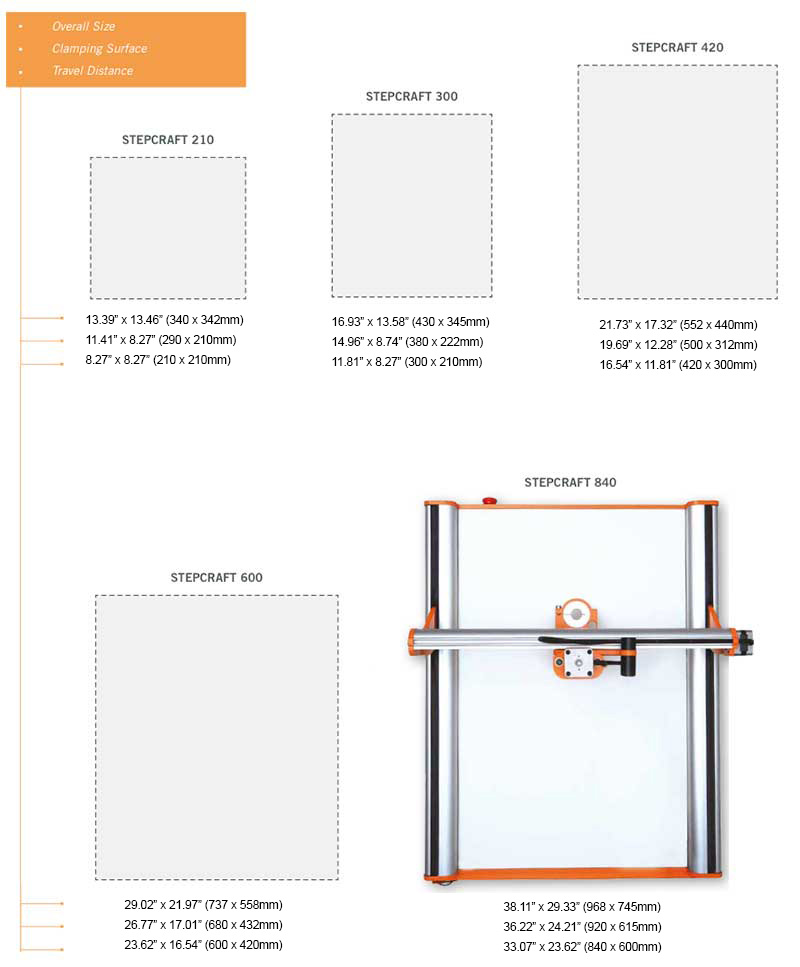
STEPCRAFT CNC machines have two parameters in the specifications for their machines: Clamping Surface and Travel Distance
Clamping Surface is maximum size of work material that you can place onto the machines bed. Travel Distance is the maximum amount that the gantry and cutting bit will move.
As an example, the STEPCRAFT-2/300 has a clamping surface of 14.96″ x 8.74″ (380x222mm) but the travel distance is equal to 11.81″ x 8.27″ (300x210mm). This means that you can place a slightly larger workpiece onto the bed than you can actually cut.
The number that is most important when choosing which size STEPCRAFT machine to buy is the Travel Distance.
The following chart reflects these sizes as well as the overall dimension of the machines. Clamping Distance is the middle set of dimensions and Travel Distance is the Lower Set of Dimensions.

The maximum speed for all Stepcraft V2 machines is 50 mm/sec (107 inches/min)
Keep in mind that there are very few materials where you will cut at full speed. Many times you will run closer to half the speed but you will be able to take deeper passes. The actual speed that you will run at will largely depend on the material and the end mill (bit or cutter).
What is the maximum project height I can 3D print?
The maximum print height is as follows:
STEPCRAFT 420, 600 and 840 – 120mm (4.72″)
STEPCRAFT 300 – 92mm (3.62″)
If you are using the STEPCRAFT Heated Bed, then you need to subtract 17mm (.67″) from the total print height.
What is the maximum height of the work material that I can place on the work bed?
The total travel distance for the Z axis is 5.5″. However, you need to keep in mind that some of that height will be used up by the systemheld tool that you place on the machine. For example, the HF500 spindle and collet stick below the tool holder by about 1.2″ This would reduce the total material height to 4.3″ From that you need to account for the length of the tool as well.
The main difference is in the physical size, specifically in the X and Y dimensions. However, the model 300 does have a shorter Z axis dimension of 3.12″ versus 5.5″ on the 420, 600 and 840 models.
The speed, controller board, software and functionality of each machine is exactly the same.
What is the difference between the Kress, HF-500, Dremel and Dewalt spindles?
We made a video to fully answer this question.
NOTE: The new HF500 spindles NO LONGER come with an air pump as we use sealed bearings and the pump is no longer required.
The level of accuracy that you will achieve with a STEPCRAFT CNC is based a lot on how well the machine was assembled and how well it is maintained. If your machine is setup with a lot of movement in the gantry and lead screws, this will equate to less accuracy at the bit. However if you take the time to not only setup and maintain the machine properly, but also take the time to do the software backlash compensation, then you can see accuracies of .001″ or better. On average a customer can expect .0015″ – .003″ of accuracy in their machine.
What is G-Code?
G-Code is the generic name for CNC machine control language. It is the way that you can tell a computerized machine (CNC machine) to make something. G-Code consists of instructions that tell the CNC machine where to move, how fast to move and what path to follow. As the machine is following the G-Code, it is continually removing material (except in the case of a 3D printer, where it is adding material) leaving behind a finished part.
You do not need to know how to program G-Code to run many of today’s personal desktop CNC machines. STEPCRAFT recommends using CAD/CAM software like Fusion 360, Vectric VCarve, Cut 2D or Cut 3D or Deskproto. These programs have an intuitive graphical interface that allows you to set all of the parameters for your job and then the software will output a fully-formatted G-Code file that you can load into your CNC’s machine control program to run the job.
It is, however, not a bad idea to learn the basics of G-Code so if there was ever a problem with a job, you can quickly reference the code and see and understand what the machine is doing (or supposed to do) for the given G-Code commands.
The short answer is that both will work, however, if you are looking for high accuracy then a screw drive system will outperform every time.
Belt-Drive Systems
Belt drive systems are much cheaper to produce and require less expensive components to make them work. A belt drive system is usually a one to one ratio between motor movement and gantry movement. Meaning that there is no gear reduction so as the motor moves, the gantry will move an equal amount. Because of this, the motor on a belt drive system will usually be much larger than a same size lead screw driven system. Belts are also more susceptible to stretching and wear. This will always affect accuracy. If the belt stretches that will immediately translate into an inaccuracy at the bit into your workpiece. Some might argue that a belt drive system will move the gantry faster, but keep in mind that moving faster into a material and having stretch on the belt will cause deflection and the belt will act more like a spring thus increasing the risk for lost steps and positioning.
Screw-Drive Systems
A screw driven system usually consists of a threaded rod (screw) that is either an Acme-type lead screw or a ball screw. The motor will rotate the screw and the gantry is attached to the screw with some type of threaded nut (lead screw nut or ball nut). As the screw turns, the gantry is moved in the corresponding direction. The number of threads per inch will determine how many rotations the screw must turn for the gantry to move one inch. This gear reduction means that you can either use much smaller stepper motors to control the movement and still maintain a very high accuracy, or you can use a larger motor and move a larger mass as compared to using the same size motor in a belt driven system. You will find much better repeatability and accuracy in a screw driven system with minimal to no linear free play. Due to the costs of lead and ball screws and components, you will find that these type of drive systems will cost more than a belt drive system.
Summary
If you are looking for high accuracy, a more rugged design, or if you plan to cut harder materials like hard plastics, hard woods and metals, then you will want a system that uses a screw-drive. If you are just planning to cut thin, softer materials like soft woods and plastics and accuracy is not as important to you, and if you do not have a large budget, then a belt-drive system might be right for you. Always keep in mind when looking at purchasing a CNC system what you might need in the future. You might think that your immediate need to make model parts out of thin plywood, thin plastic and balsa wood might not require a screw drive, but maybe in the future you want to cut hardwoods, thicker plastics or metals, or you get a project that requires a high cutting accuracy – in this case you might be kicking yourself for not spending the extra few hundred dollars for the better drive system.
Fortunately there are not a lot of things that will break on the STEPCRAFT CNC, however from time to time, depending on how well you maintain the machine, you might have a part or two wear out and need to be replaced. When this happens, simply call or email our support department and they will take care of sending you a replacement part right away. There is a full two year warranty for all STEPCRAFT machines. If you need assistance replacing the part, STEPCRAFT’s support department can walk you through it on the phone, send you a how-to video or arrange a video conference call to help you though the process.
In extreme cases, where a customer has a machine that has not been assembled properly and needs support’s direct assistance, you can send it back to STEPCRAFT and the support team will fix/adjust, test, repackage and send back to you. This is a very rare scenario as 99% of the problems can be resolved quickly over the phone.
It allows you to automatically set the Z height to your workpiece top surface or your machine’s bed surface.
To use it, you simply place the sensor on top of your work material or on top of your bed, and then move the gantry so the tip of the end mill is just about the button on the sensor. Then you can press the Tool Length button on UCCNC and it will automatically lower the bit until it touches the sensor. Once complete you remove the sensor and when you press “Go to zero” on UCCNC you will notice that the tip of the end mill is exactly on top of the workpiece’s surface.
Here is a video that explains how to set it up and use it:
You can think of the Semi-Closed Loop System as an “electronic insurance policy”. The system uses a special sensor that is installed on each of the 4 CNC motors. This sensor monitors the movement of each motor and compares that movement against what UCCNC is telling it to move.
As an example, if UCCNC wants to move X 35mm to the right and something is interfering with that movement and it only moves 31mm, then the Semi Closed Loop System will immediately stop the system.
The beauty of this system is that you can simply rehome the machine and then continue the job right where you left off. This is especially handy when you are using expensive materials that you do not want to waste.
What do I need to run the Oscillating Tangential Knife OTK-3?
The Oscillating Tangential Knife requires no special software outside of the standard CAD/CAM program used to design and create toolpaths. Cut2D, VCarve Desktop and VCarve Pro are all compatible with the OTK-3. As of May 2019, the only “special” software needed to run the knife is the free version 1.2110 of UCCNC.
Securing your workpiece for use with the OTK-3 may require use of a vacuum table or sticky table, as materials such as hard foam, cardboard, leather, cork and carpet can be tough to hold with traditional clamping methods.
To be able to make your first CNC project, you need, at minimum, the following items:
- CNC base machine (STEPCRAFT 210, 300, 420, 600 or 840)
- A Spindle (HF500, Kress, Dremel, Dewalt, Proxxon, etc). Please watch this VIDEO for an explanation of all our spindle options.
- Tooling (also know as “end mills”). You will need an end mill for the particular material that you intend to cut/carve. STEPCRAFT sells a Starter Tool Set that comes with an assortment of tools to get you started cutting and carving woods, plastics, aluminum, carbon fiber, composites and two bits are included for engraving.
- CAD/CAM Software. STEPCRAFT includes a free year subscription to Fusion 360, which is a very powerful 3D design and CAM software system. However, Fusion 360, while powerful, is also time consuming to learn and become proficient at. STEPCRAFT also sells Vectric programs (Cut 2D, Cut 3D and V Carve). These programs are better suited for the beginner and will have you up and running with your first projects in a matter of minutes.
NOTE: Having a copy of a Vectric program is a good idea, even if you intend on learning Fusion 360. Vectric programs are quick and easy to setup a job where Fusion will become quick once you learn how to use it. Think of Vectric programs like a sprint and Fusion 360 more like a marathon when it comes to the end result with creating CNC projects.
That’t it! These are the minimum things you need to get started with CNC’ing. You can also check out STEPCRAFT’s Complete System Packages for preconfigured systems that come with everything you need to get started as soon as you receive your new CNC system.
STEPCRAFT CNC machines are sold in an a la carte fashion were you purchase the base machine (210, 300, 420, 600, or 840) and then you can customize your system with any of the systemheld attachments, accessories, or software programs that we offer.
The base STEPCRAFT CNC machine will come with a UCCNC, which is our machine control software. This program will allow you to configure, move, jog and setup the machine as well as run G Code files to operate the CNC. You can think of UCCNC as an “operating system” for the STEPCRAFT CNC.
Additionally, you will receive a UC100 Parallel to USB interface with your STEPCRAFT. This device allows you to connect to your computer using a USB cable. The STEPCRAFT uses a parallel bus on its control board, which is very common in the world of CNC router systems. Parallel busses are very fast in comparison to a serial bus system. Since many projects that you could run on your CNC might contains tens or hundreds of thousands of lines of code, it is important to have a fast control board architecture. The problem with this is that it is very uncommon to have a parallel interface in a modern computer. USB, Firewire and Thunderbolt are the common interfaces of today. So to make sure you can use your STEPCRAFT CNC with any modern day computer, the UC100 is used.
The UC100 is a coded device, which means you can not use it without a license file that matches the device. Your STEPCRAFT CNC will come with a license file (either on a USB stick in the box or will be emailed to you). This file will be placed in the UCCNC folder on your computer and it will automaticlly verify that your UC100 matches when you start UCCNC.
Every new STEPCRAFT CNC sold in the USA, Canada and Mexico will include a card which gives you a full year of Autodesk’s Fusion 360 CAD/CAM software for free. Fusion 360 is a very powerful 3D CAD/CAM package that will really extend the limits of what you can create on a STEPCRAFT CNC. There is more of a learning curve for Fusion 360 than there is for other programs like the Vectric and Deskproto programs.
The STEPCRAFT CNC does not include CAD/CAM software (other than the free year of Fusion 360), a spindle, tooling or other accessories or attachments. You will need to purchase these items separately or you can consider purchasing a Complete System Package, which will come configured with everything you need to get started as soon as your machine arrives.
What clamping system comes with the Stepcraft CNC system?
The Stepcraft CNC machines come with a White Formica hardboard table and a pair of cross clamps that fit into integrated slots in the inner frame of the machine. These cross clamps have bolts in them which will allow you to secure material up to about 1/2″ in thickness. Another alternative for fastening material is to use double sided tape and stick it to the white top. This will securely hold the material in place while you cut it. Another common practice is to cut a piece of 3/4″ MDF to the size of the word table and secure that to the white surface using double sided tape. This will also act as a waste board and it will allow you to screw material into the board to secure it.
Stepcraft also sells a T-slot table option for all of their machines except the 210. This will allow you to clamp the material using either Stepcraft Clamps or a variety of aftermarket T-slot clamps.
In most cases you will need some sort of waste board under your work material to prevent you from damaging the white table or T-slot table.
What are the differences between the 5 different STEPCRAFT Desktop CNC models?
The STEPCRAFT 210 is based on a version 1 of the STEPCRAFT CNC product line. It will have a very small work area as well as a max speed of around 30mm/sec and a lower Z height (around 3″). The STEPCRAFT-2/300 has the same specs in terms of speed and functionality as the 420, 600 and 840, but the Z height is slightly shorter (around 4″) as compared to the 5.5″ of the other machines. The STEPCRAFT-2/420, STEPCRAFT-2/600 and STEPCRAFT-2/840 all have the same basic specs with the exception of the total work area size in the X and Y dimensions. The following chart will help illustrate the differences between the different size STEPCRAFT desktop CNC machines.
All STEPCRAFT software, including UCCNC and Vectric products require a Windows-based computer system or a Mac running Parallels with Windows.
- COMPUTER:
- 2 GHZ multi-core CPU
- 2 GB RAM with Windows XP (SP3), Windows Vista, Windows Version 7, 8, 8.1, or 10
- 300 Mb Disk Space (Vectric)
- 100 Mb Disk Space (UCCNC)
- DISPLAY
- 1024 x 768 graphics display
- OPERATING SYSTEM
- Windows XP (SP3), Windows Vista, Windows Version 7, 8, 8.1, or 10 with 2 GB RAM
If you wish to run Fusion 360, that can be run on both Windows machines and Mac computers natively.
STEPCRAFT offers financing through Crest Financial. You can fill out the application at www.stepcraft.us/crestapp
Keep in mind that STEPCRAFT has no control over the financing approval process. Crest will approve you for a specific amount of money of which you can apply all or some of it towards your purchase. Your Payments will be made directly to Crest Financial.
Yes we have a chart that shows all 5 machines. The bottom dimensions “Travel Distance” is the largest workpiece that you can use on each machine
STEPCRAFT’s office is located in Torrington, CT. We have a full demo room that you are welcome to come and visit during normal business hours or at other times by appointment.
STEPCRAFT sells direct only and not through dealers in the USA, Canada and Mexico. Our reason for doing this is so that we can maintain the best possible customer service for our customers. When you call or email us, you are speaking to a representative that ONLY sells and supports STEPCRAFT CNC machines.
If you are located in an area that is too far away to visit, we will work with you and do our best to make videos, and test your files and materials to ensure that the system will meet your needs and expectations.
STEPCRAFT’s office in Europe is located in Menden Germany. In addition to selling directly, they have an extensive dealer network in many different countries to best support and service customers in their native language and in reasonable geographic range. You can see the full list of dealers by clicking HERE.
Is the STEPCRAFT CNC system able to engrave or cut through carbon fibers?
Yes, the STEPCRAFT CNC will cut carbon fiber very well and very accurately. However, due to the hazardous nature of the carbon dust, STEPCRAFT has a Milling Bath that can be used where you cut the Carbon in water and the water captures the dust not allowing it to become airborne. You can see the Milling Bath here: https://stepcraft.us/product/milling-bath-840/ (They are available in sizes for the 420, 600 and 840 machines)
The following videos show you how well a STEPCRAFT can do with Carbon Fiber:
If I use Solidworks CAM or Fusion 360 CAM, do I still need to use UCCNC or Mach 3?
The purpose of any CAM program is to take your design file and turn it into G-Code by assigning tool paths to your project and outputting it in a format that a CNC machine can understand.
That being said, you still need a method of controlling the CNC machine, which is where programs like Mach 3 and UCCNC come in. They are designed to connect to the CNC machine and the G-Code files that you create in your CAM program are loaded into Mach 3 or UCCNC to run the machine.
With any CNC router, you have three main steps to creating a project:
- Design your project in a CAD/Drawing program
- Use a CAM program to assign tools and tool paths to the project
- Use a machine control program to load the G-Code files and run the CNC machine.
If I order a STEPCRAFT with an Automatic Tool Changer, will you pre-install the tool rack and setup the software?
Yes we can pre-install the tool rack(s) for you on your machine. We will ALWAYS put them in the rear right corner (when looking from the front of the machine). Additionally, we will setup the tool locations in UCCNC and send you the Macro file that you can simply copy to your installation of UCCNC. Once complete, all locations should be correct and you can start using the ATC right away.
If I order a STEPCRAFT CNC Ready To Run with a Tool Length Sensor, will the sensor be ready to use when I get the machine
When you order a Tool Length Sensor with your Ready To Run STEPCRAFT CNC, the tool length sensor will be wired and ready to use. You will have to install the macro for the tool length sensor (see video below) into your computer to get it to work. Depending on when you purchase your machine, the Tool Length Sensor will either be wired in directly to the machine, or there will be a headphone jack that you can plug it into coming out the back of the machine.
If I order a STEPCRAFT CNC Ready To Run with a 4th Axis System, will the 4th Axis be ready to use when I receive it?
The 4th Axis unit requires a board that must be plugged into the main circuit board on the STEPCRAFT. This board will be installed on Ready To Run machines. The only thing you will need to do is to mount the 4th Axis unit and Tail Stock on the T-Slot table and plug the serial cable from the 4th Axis unit into the board.
Note: it is recommended to maximum flexibility for stock size and ease of use that you purchase a T-Slot table for your STEPCRAFT CNC.
If I am from the USA, Canada or Mexico, does my machine get shipped from the Germany Headquarters?
No, Your order will ship from Torrington, Connecticut. Additionally, all post-sales support will also be done from our Torrington, CT office.
With well over 6500 STEPCRAFT systems sold around the world, there stands to reason that a small percentage of customer might have some trouble. The instructions are very well thought out for any level of builder, but still, you MUST follow them step by step. Additionally we produced a Assembly Training Course that is a video tutorial outlining every step in the manual. Between the manual and videos, the average customer should not have any trouble.
We find that many customers who you are reading about either do not have the skill set to understand basic assembly terminology or are skipping steps in the assembly process. Many times a quick call to our support team has the customer up and running quickly.
There are no special tools or skills required to assemble a STEPCRAFT kit, but if you are the type of person who “skims” through manuals and are not detail oriented when assembling something, then you might have the same issues that some people post about. While it is not a hard build, there are a few items that you must pay attention to due to the precise nature of the machine.
If you take your time and follow the steps in the videos and manual, you will not have any problems building your STEPCRAFT CNC.
I want to buy a STEPCRAFT Complete System package, but I want VCarve Pro rather than Desktop, how can I do this?
All of the complete system packages, with the exception of the ELITE comes with Vectric VCarve Desktop software which will have a 24×24″ size limitation. If you are looking to order the 840 CNC, then you will NOT be able to use the entire work bed with a single file using VCarve Desktop. So you would need to VCarve Pro. You can click this link https://stepcraft.us/product/package-upgrade-to-v-carve-pro/ to add the “UPGRADE” to your order. Please NOTE that this is ONLY the upgrade and can only be used in conjunction with a complete system that has VCarve Desktop.
It really depends on what you are using for a spindle, bit and what type of material that you are using. Statistically larger diameter bits will produce more noise. The same is true for using a router as a spindle instead of a CNC spindle like the HF500 from STEPCRAFT. It also depends on what you are using for attachments. For example, if you are using the 3D Printer, foam cutter, drag knife, engraving point or wood burning pen, then the only noise you will hear is the rhythmic whine of the stepper motors working in unison together. If you are using a Dewalt DW611 router with a 1/4″ end mill then the noise will be much greater; about the sound of an electric hand mixer but not as loud as a blender.
If noise is a concern for you, then you can consider getting a STEPCRAFT Enclosure which will reduce noice by as much as 50%.
How much of STEPCRAFT CNC machines are “Made In Germany”?
Quality standard of STEPCRAFT products
The machine series STEPCRAFT 210, 300, 420, 600 and 840 grant the designation “Made in Germany”. With respective to the objective of value and origin of the individual components nearly 90 % comes from German suppliers:
| Value percentage % | Germany | Switzerland, China |
| Electronics & Software | 33 % | 3 % |
| Mechanics | 56 % | 8 % |
| Total | 89 % | 11 % |
Most of the suppliers have their head office not far from Menden, the location of STEPCRAFT. The advantages are clear:
– Availability of replacement parts
– Quality assurance of the manufacturing process
– Short fabrication and delivery times
– Better transparency and value for money
– Optimization of logistical processes
– Quick response times
How much are STEPCRAFT CNC machines?
All of the pricing for STEPCRAFT products are located on the website at www.stepcraft.us. Everything on the site is setup to purchase separately. For example, You pick the machine that you want (300, 420, 600, 840, etc) and then you choose your spindle, followed by other attachments and accessories. To make buy easier we also put together some Complete System Packages that include the machine, spindle and all necessary software and accessories to get you up and running as soon as you receive it.
On average it takes between 8-10 hours depending on your skill level. The kits are not hard to assemble and there are no special tools required. We also have an online video training course that walks you though every step of the assembly process.
There are three basic software program types that you will need to have some knowledge of when getting ready to use your STEPCRAFT CNC system:
- A design or CAD program. Design programs like Adobe Illustrator, Inkscape, Corel Draw. CAD programs like AutoCAD, Fusion 360, Sketchup, Solidworks, etc. STEPCRAFT supports these and many more of the popular CAD/vector design software programs on the market. Depending on what you are looking to do will determine how much knowledge you will need to have on a CAD or design program
- A CAM (computer aided manufacturing) program. A CAM program will take the vectors or 3D model that you have designed and allow you to tell the program which tools you intent to use as well as the material size and the speeds and feed rate that you wish to run for your project. The CAM program will output a G Code file, which is basically common machine language for CNC machines. Vectric programs like V Carve and Cut 2D make this process pretty easy. STEPCRAFT sells and supports the full line of Vectric programs as well as Deskproto Multi-Axis CAM software.
- UCCNC (or machine control software). This program is used to setup, job and zero the STEPCRAFT CNC as well as loading and running the G Code file that was created from your CAM program.
So answer the question as to how easy it is to learn, really depends on what you are looking to do.
For example, if you are looking to do projects that are pretty complex and require that you design them in Fusion 360 or Illustrator, and you DON’T know how to use these programs, then you will have a longer learning curve since you will have to learn the design program as well.
Assuming that you already know how to use a design or CAD program, then the next program you would need to learn is a CAM program, such as Vectric V Carve. The nice thing about V Carve (or Cut 2D) is that the interface is very easy to learn so you can be on the way of making your first CNC project in a matter of minutes. However, as you progress, these programs have a lot of powerful features that will extend the limits on what you can create on your STEPCRAFT CNC machine.
As for UCCNC, this program takes about 15 minutes to learn how to use. Much of what you see on the screen are buttons and features that you will not use (unless doing advanced features like automatic tool changing, etc). There are only about 5 buttons that you will need to focus on to successfully start creating projects on your STEPCRAFT right away.
This video gives you a basic overview of the software programs and how easy it is to get started right away.
How early do I need to order a machine assembly kit, to have it arrive before Christmas?
We would recommend that you order at least 3 weeks before Christmas for a KIT machine to ensure Holiday delivery. If it is an assembled machine we recommend purchasing at least 4 weeks ahead.
It is comprised of 4 sensors, one mounted on each of the Y-axis motors, one on X and one on Z. The sensors monitor the motors’ movements and compare that movement against what UCCNC (your project’s G-Code file) is telling the motor to move. In the event that one of the motors does not match the intended movement, then the system will immediately go into E-Stop.
As your machine is cutting a project, if it runs into an obstruction, or if there is any other situation that causes the machine to stall in one of the axes, it will stop the system.
To reset, you can simply rehome the machine and then continue running the job from where you left off. You can use the RUN FROM HERE button on UCCNC and the job will continue as if the error never happened. You can watch the following video to learn how to use this feature on UCCNC:
Many CNC machines will offer a dust boot or adapter that surrounds the spindle with a brush or rubber gasket material that rubs along the workpiece. A vacuum is connected to this adapter and dust is extracted right at the end mill. STEPCRAFT, for example, offers an exhaust adapter with a removable brush.
To get the most out of your dust collection system you need to make sure that the brush is contacting the work surface. If not then only a percentage of the dust will be drawn into the dust collection system. Depending on the system you might need to use shorter bits to achieve this.
To extract the dust you can use a simple shop vac or an integrated dust collection system.
If an error has occurred or your system has an obstruction causing the Semi-Closed Loop System to trigger, it will activate the E-Stop mode on the machine. When this happens the first thing you need to do is take note of the line number that you are at in the G-Code window on the lower left part of the UCCNC screen. Write it down or take a photo with your cell phone.
To reset this, you press the Red reset button on the UCCNC screen and then press HOME ALL. This will reset each axis so that everything is back in sync with UCCNC. From that point, you can use the START FROM HERE button and restart the job from right where you left off.
You can view this video on how to use the START FROM HERE button:
Using a CNC machine is like an artist painting.
The material you are working on is your “canvas” and the bits (otherwise known as “end mills” or “tools”) are the “brushes”
There are literally tens of thousands of bits available for a CNC machine from hundreds of manufacturers. Getting into detail on them all would literally be a book. So for this question we will break it down into XX types:
Square nose end mill – These bits are the most common and are what you would likely turn to for all of your CNC cutting. They come in a variety of shapes, sizes and spiral types. If you are just starting out, you might want to have an 1/8″ 2 flute up spiral and a 1/8″ 2 flute down spiral end mill to get you started. Both bits will work in most all CNC machines as an 1/8″ shaft diameter is very popular, even if you are using a Dremel tool as a spindle.
2 Flute is a common type since most CNC routers run at very high RPM, so you need fewer flutes to extract the chips from the material as you are cutting quickly.
Up Spiral bits will pull the chips away from the material, but can leave a frayed top edge of your workpiece, these bits are better for plastics and aluminum and harder woods.
Down Spiral bits will push the chips into the work material but will leave a very clean top edge cut. These bits are best for softer materials and wood as they leave a better finish. They also force the material down into the bed of the machine which is good for thinner materials, where an up spiral bit will tend to pull it away from the bed.
Ball Nose End Mill – These bits have rounded bottom and are typically used for carving 3 dimensional projects. When used properly they can leave a very smooth and detailed finish on your workpiece.
If you are just starting out, I would get a 2 flute 1/8″ and 1/16″ ball nose for your tool kit. These two sizes are very common and depending on the level of detail, you would have a bit for most requirements.
Engraving Bits – These bits will have a V point on the end are used for engraving materials for lettering or designs. Its suggested to have 1/8″ 90 degree and 60 degree engraving bits for your tool kit when you are starting out. These will give you a lot of flexibility for engraving options.
Additionally, if you have a CNC that can support 1/4″ shank bits, then its suggested to get a 1/2″ V router bit with a 1/4″ shank. These are commonly found at home improvement stores like Home Depot and Lowes. This 1/2″ V bit is perfect for sign lettering and when using a program like V Carve, you have the ability to do some really nice 3D lettering.
These are the most common bits that I suggest any beginner have in their tool box. As you gain more experience, you can add many more bits to your system in a variety of shapes and sizes for different applications. STEPCRAFT has a Starter Tool Set
that includes all of these bits which can be found HERE.
This is a question that can be answered in many ways.
Use A Premade Design
The easiest way to get a project made on the CNC is to buy a design that is already done for you. You can find many for free on the internet, but a few VERY good commercial options for 2D and 3D designs are:
- www.makecnc.com – Excellent selection of puzzles and other creative projects.
- www.designandmake.com – Very high quality 3D projects that can be reworked into hundreds of different possibilities.
- www.thingiverse.com – large selection of free 3D designs. Most are for 3D printing but many will work with a CNC as well.
- https://woodgears.ca/gear_cutting/template.html – Gear designer
- http://www.vectric.com/cool-stuff/projects.html – 2D and 3D high quality project files
- www.cnccraze.com – many project files
Bitmap Image Trace
Another option that is no as easy as just buying a file or downloading something that has been already designed, but is still easier than designing something from scratch, is to import an image or logo (i.e. from Google Images) and use the Image Trace feature in Vectric to create a vector from the bitmap image. Once it has been converted into a vector, you can assign tool paths to it and proceed to cut out on your CNC.
Another way to convert your bitmap images to vectors is to use the site (or software) https://vectormagic.com/. The online version of their program works very well and returns a vector that has excellent quality.
The following video shows you how to use Vectric’s Image Trace feature
Design Your Own
Sometimes you can not get exactly what you are looking to create from an online source that is pre-made, so you must turn to making your own design. This is not as scary as it sounds, especially if you are looking to cut out simple things like letters, signs, etc. The CAD (or design) part of Vectric programs make this easy. Cut 2D and V Carve have a design component to their software and you can quickly and easily design many different projects and then switch to the CAM part of the program to create the tool paths and output the G Code to the CNC.
You can also create vector designs with programs like Corel Draw and Adobe Illustrator, or if you need something designed to very specific dimensions, you can use a CAD program like Fusion 360 or Sketchup.
Hire Someone To Design For You
There are many outsourcing websites on the internet where people are looking for design work. You will be find many very talented people from all around the world and many (depending on the country) are willing to work for very reasonable rates.
www.upwork.com is one site where you will be able to post your job and have people bid on the project. You can read up on the applicant, discuss specifics and finally hire the person who best meets your needs.
You can go on websites like www.cnczone.com or the Facebook Group CNC Router Tips and put a post up with what you are looking to have designed and more often than not, you find people who are willing to do your design for a small fee (if not for free)
CNC Manufacturer
If all else fails, then contact the manufacturer of your CNC machine and ask them if they can help with the design or if they know anyone who you could contact.
YouTube is also a good source to find how-to videos that can show you how to make your designs or how to use various software programs.
STEPCRAFT CNC systems require that they are connected to a computer via a USB cable. Having the machine connected to a computer may not be as convenient but the ability to make file changes and reset parameters of the CNC from the computer saves a lot of time.]
Does the 3D Printer attachment fit all size machines?
Yes, it will work with all Version 1 and Version 2 STEPCRAFT CNC machines.
Does STEPCRAFT have an online forum?
Yes, it is located on our German website at https://www.stepcraft-systems.com/en/service-and-support/stepcraft-forum-uk
There is also a Facebook group called the STEPCRAFT Crafter’s Club that is very active as well. You can visit that at www.stepcraftcraftersclub.com
Does Deskproto Multi-Axis Hobby Edition have the ability to use the entire bed of the STEPCRAFT-2/840?
Yes, there are no size limitations to Deskproto Multi-Axis Hobby Edition. For more information on Deskproto Multi-Axis please click HERE
To Purchase a non-commercial hobby license please visit https://stepcraft.us/product/deskproto-multi-axis-hobby-license-non-commercial-use-only/
![]()
Yes we do. Please contact our Education Sales Manager, Dawn Constantiello (dawn@stepcraft.us) for more details.
Yes, ALL Machines and most attachments come with a printed manual. Some newer products or smaller attachments might only come with a PDF manual which you can download by clicking the “DOWNLOADS” tab from the product page on the website www.stepcraft.us.
Do I need to buy additional software if I am only buying the Machine and 3D Printer attachment?
No, since UCCNC is included with the machine to run the G Code and the 3D Printer attachment comes with Repetier-Host slicing software. Those two programs are all you need if you are just going to use your STEPCRAFT CNC for 3D printing. If you are going to use the machine for cutting (spindle, laser, drag knife, etc.) then you need to have a CAM software program as well.
When you buy an Automatic Tool Changer (ATC), the system might come with an orange switch box. That switch box is intended for use with the ATC on the D.Series line of CNC machines as well as the M.Series machines that DO NOT have a Tool Magazine on the back of the machine. If you did not purchase the optional Tool Magazine then you would need to use the Switch Box. If you have the Tool Magazine, then you DO NOT need to use the switch box.
Do I have to design my files in metric because I see that UCCNC is metric?
No, You can design in inches or metric. If you are using Vectric programs, you can design in inches or metric because when you choose the post processor to create your file, the post processor will convert the G Code to metric.
For more information on which post processor to use, please see this FAQ: https://cncfaq.us/ufaqs/post-processor-use-vectric-programs-vcarve-cut-2d-cut-3d-photovcarve/
No, at this time you can not use it because the Exhaust Adapter wraps around the whole spindle, which will interfere with the tool changer putting the tool back into the rack. At this time we do not have plans for a new exhaust adapter design that will be able to be used with the tool changer.
If you wish to learn the Vectric software while you are waiting for your STEPCRAFT CNC to arrive, your best bet is to download a FREE full working trial copy of the software from Vectric’s website.
The trial versions will not allow you to save a toolpath for your CNC other than the special sample files that are included. However any files that are created and saved with the trial versions of Cut2D, VCarve Pro, Aspire or Cut3D can be opened and made fully operational once you purchase and install the full version of the software as long as it is installed on the same PC as the trial version software.
Important: Please note that the Trial version of the software cannot be ‘Activated’ with the license key you receive when you purchase a copy. The trial versions of the software are for testing and evaluation only. It is not possible to license them to become full versions. You will however be supplied with a CD with your order which you can install and overwrite the trial copy.
Can you scan your own design and create a tool path to cut the object out on a CNC (Image Tracing)?
Vectric software, such as Cut 2D and VCarve have the ability for you to import a bitmap image and then use a function called “Image Trace” to create a vector around the image. You can then adjust and modify the vector to your liking. From there you can select the vector(s) and create a tool path for the CNC machine to cut around. You can also vary the depth of the cut to meet your specific needs.
The following video show you how to do this:
No, the STEPCRAFT is only designed to cut non-ferrous metals like brass, aluminum and copper. You might be able to engrave steel with the right engraving bit and proper speed and feed settings, but you can not cut it.
Can I use Solidworks CAD/CAM software with a STEPCRAFT CNC?
Yes, you can use Solidworks CAD. Simply output the files in formats that are compatible with Vectric software (DWG, STL, etc.). As for the CAM part of Solidworks, as long as you can out put standard G Code, we find that it will work without problems. If there is a post processor for Mach 3, you can use that and the G Code will have the proper formatting for Stepcraft.
Can I use an American Express card to buy a STEPCRAFT CNC?
Yes you can, but you need to select PAYPAL at checkout and then when you get to the PayPal page, there is a link at the bottom of the page to pay with your Credit Card. You do NOT have to log-in to a paypal account to use Paypal as a card processor this way.
You should be able to use Visa, Mastercard, AMEX and Discover.

Can I use a Mac with a STEPCRAFT CNC?
Yes! While the UCCNC and Vectric Software both run on Windows platforms, you can use a MAC as long as you run Parallels software which allows you to install Windows on your Mac. You can not run UCCNC or Vectric natively on a Mac (without Parallels). If you use Fusion 360 for CAD/CAM, then you can install that natively as they have a Mac version of that software. However, UCCNC will still need Parallels with Windows.
NOTE: Since a Mac computer is typically much more expensive than a Windows system, and the fact that UCCNC does not need a powerful computer, we recommend using your Mac for the design work and then getting an inexpensive or refurbished computer (desktop or laptop) to use to run the CNC, since the area around the CNC can potentially have dust and chips that might get on or near the computer.
Can I use a 3D scanner to create 3D models to carve as well as 3D print?
Yes, models created with a 3D Scanner are typically saved in common 3D formats like a .stl. These files can be imported into CAM programs like Vectric Cut 3D, Vectric V Carve and Deskproto where they can be assigned tool paths to carve the object out of a material. This is commonly done with two tool paths: Roughing and Finishing, using a standard end mill and a ball nose end mill, respectively.
These files created from a 3D scanner can also be used for a 3D printer.
Here is a good article with a list of the best 3D scanners for 2017: https://pinshape.com/blog/the-11-best-3d-scanners-on-the-market/
STEPCRAFT also has a 3D Touch Probe which can be used for 3D scanning. The following videos show how that works:
Yes you can download a full working trial copy for free. Please see this FAQ
STEPCRAFT only accepts purchase orders from schools and government agencies at this time. All forms of payment are accepted (Cash, Credit card and Paypal). If you wish to pay by check, you can mail the payment to us, but we do require that the check clears before we will ship your order (3-5 business days).
Can I order a STEPCRAFT Package Bundle as a Ready-To-Run (RTR) unit?
Yes you can but we do not have an option for this on our website. We only have an option on the site for the individual machine; to order as a RTR. If you wish to order a package, please contact our sales department at 203-556-1856 or email info@stepcraft.us.
The charge for assembly, test and crate is $499.00
At this time, the only financing companies that we work with finance only to customers in the USA. One option for Canadian customers is to use Paypal Credit. If you have a Paypal account, you can apply online and get an approval right away. You can also talk with your local banks or credit unions in your country.
Can I engrave a photograph into a piece of wood?
Yes, you can use Vectric’s PhotoVCarve program, which allows you to create an engraving tool path for photos.
Additionally, you can use the new Laser Engraving Head DL445 which can laser engrave your photos into a variety of materials.
Can I cut carbon fiber on the STEPCRAFT CNC?
Yes, you can. In fact, carbon fiber cuts very easily on the STEPCRAFT. The main issue with cutting carbon is the dust that is created is very hazardous to your health if you breathe it in. To combat this, STEPCRAFT has a Milling Bath in three separate sizes for the 420, 600 and 840 machines. You can find information on the Milling Baths here: https://stepcraft.us/product-category/accessories/system-accessories-accessories/cnc-accessories/
Additionally here are a couple videos that you can watch containing more information on using a STEPCRAFT CNC for carbon fiber.
Can I buy the STEPCRAFT Touch Probe for use with a non-STEPCRAFT CNC machine?
Yes, you can purchase the Touch Probe and it will most likely work with just about any CNC. However, you be responsible for the correct software setup, macros and configuration for your system. STEPCRAFT will NOT support the operation or configuration of the Touch Probe for non-STEPCRAFT machines. The unit will, however, be warranted for mechanical defects.
Yes, you c an buy the machine fully assembled, tested and crated. There is an additional charge of $499. Since the machine is crated, all size D-Series machines must be shipped via a freight company which will incur an additional cost over shipping a KIT via UPS.
With STEPCRAFT CNC machines being in such a high demand around the world and the pricing on STEPCRAFT systems being very competitive, it is not very often that Soeca
From time to time around various holidays, STEPCRAFT will run a promotion and have a discount code available. This happens around Black Friday, Christmas and Mid Summer. These discounts could range from free shipping to a few hundred dollars of a complete CNC system. Be sure to check out Facebook page for details on any specials that we might be running. www.facebook.com/stepcraftinc
Are there any specific 3D Scanners that work best with STEPCRAFT, or any other CNC?
Honestly, No. Most 3D scanners are capable of generating and saving files in common 3D file format. That is really all that is required for STEPCRAFT. The resolution will vary, though, from scanner to scanner and typically the more expensive they are, the better the scan resolution:
Here is a good article with a list of the top 11 3D scanners for 2017: https://pinshape.com/blog/the-11-best-3d-scanners-on-the-market/
Are all of the machines capable of using the spindle, laser and 4th axis?
Yes, you can use all of these attachments on each of the machines. However the small size of the STEPCRAFT-1/210 might make it tough to use the 4th axis with longer work pieces. Additionally, the 210 has a limited 3″ Z height, which does not leave a lot of vertical travel and will limit the diameter of material that you can use on the machine. Additionally you really need a T-slot when using the 4th Axis so you can adjust the tail stock for the length of the work material and the 210 is the only machine that does not have a T-Slot option.
Deskproto CAM Software
Does Deskproto Multi-Axis Hobby Edition have the ability to use the entire bed of the STEPCRAFT-2/840?
Yes, there are no size limitations to Deskproto Multi-Axis Hobby Edition. For more information on Deskproto Multi-Axis please click HERE
To Purchase a non-commercial hobby license please visit https://stepcraft.us/product/deskproto-multi-axis-hobby-license-non-commercial-use-only/
![]()
Education
Why is My UCR201 Jog Pendant Not Showing Up In UCCNC?
The UCR201 Jog Pendant requires the user to enable the plugin in the configuration window in UCCNC. If you are running version 1.2037 of UCCNC, you may find that the Jog Pendant does not show up in the configuration window. If this is the case, you simply need to update UCCNC to a newer version which can be found below…
UCCNC Version 1.2049 – http://www.cncdrive.com/UCCNC/download_UCCNC.php
After downloading and installing version 1.2049 of UCCNC, the Jog Pendant should now be visible in the configuration window and you can proceed with the rest of the setup!
Why is my project coming out incredibly small?
If your project is coming out incredibly small in UCCNC (e.g. 1/10th the size designed) you are most likely using the incorrect post processor. Every post processor used with a STEPCRAFT machine should end in (mm). This is because UCCNC will only accept millimeters as a parameter! Even if your project is designed entirely in inches, the (mm) post processors will automatically do the conversion from inch to mm for UCCNC to properly interpret. This means that you can design in inches, millimeters or anything you choose, and the post processor will always do the proper conversions for you. It is a very common mistake to select the (inch) post processor when working in inches. This will NOT do the proper conversion and UCCNC will interpret every inch measurement as a millimeter measurement. This is why the project, when saved with the incorrect (inch) post processor, will come out very small.
What is G-Code?
G-Code is the generic name for CNC machine control language. It is the way that you can tell a computerized machine (CNC machine) to make something. G-Code consists of instructions that tell the CNC machine where to move, how fast to move and what path to follow. As the machine is following the G-Code, it is continually removing material (except in the case of a 3D printer, where it is adding material) leaving behind a finished part.
You do not need to know how to program G-Code to run many of today’s personal desktop CNC machines. STEPCRAFT recommends using CAD/CAM software like Fusion 360, Vectric VCarve, Cut 2D or Cut 3D or Deskproto. These programs have an intuitive graphical interface that allows you to set all of the parameters for your job and then the software will output a fully-formatted G-Code file that you can load into your CNC’s machine control program to run the job.
It is, however, not a bad idea to learn the basics of G-Code so if there was ever a problem with a job, you can quickly reference the code and see and understand what the machine is doing (or supposed to do) for the given G-Code commands.
What do I need to run the Oscillating Tangential Knife OTK-3?
The Oscillating Tangential Knife requires no special software outside of the standard CAD/CAM program used to design and create toolpaths. Cut2D, VCarve Desktop and VCarve Pro are all compatible with the OTK-3. As of May 2019, the only “special” software needed to run the knife is the free version 1.2110 of UCCNC.
Securing your workpiece for use with the OTK-3 may require use of a vacuum table or sticky table, as materials such as hard foam, cardboard, leather, cork and carpet can be tough to hold with traditional clamping methods.
How Can I Calibrate My Tool Length Sensor?
If you find that your tool length sensor (TLS) is functioning properly, but not touching the very top of your material, you may need to preform a quick calibration. This ensures that the tool length sensor is accurate and reliable. The following video will walk you through the simple TLS calibration…
Yes we do. Please contact our Education Sales Manager, Dawn Constantiello (dawn@stepcraft.us) for more details.
End Mills and Cutters
What is the best bit or end mill to use when cutting Acrylic, and what are the best speeds and feeds?
Acrylic is a very common material to cut on a CNC. It can be used for anything from making windows in projects to making edge-lit LED signs. Acrylic can be a tricky material to cut successfully, mainly because many people will run the RPM of the cutter too fast with a feed rate that is too slow, thus causing melting of the plastic. The trick is to get nice clean chips as you cut.
The following article goes into this in detail: Cutting Acrylic – 8 Guidelines To Getting The Best Results
What is a surfacing bit used for?
A surfacing bit typically has a larger than normal cutting diameter (1 to 3 inches) and are used to flatten or level uneven surfaces on your project material. They are also used to take the thickness of a material down to a final required size. For example, you might have a piece of rough cut lumber that measures 1 inch in thickness but you need it to be 3/4 inch thick. If you don’t have a surface planer in your shop then you can use a surfacing bit with a pocket tool path to plane the material down.

Another common use for surfacing bits is to clean up and level a spoil board. After continuous use your spoil board’s surface will have a lot of cuts in it and you might want to clean it up so it is perfectly smooth again. A surfacing bit is perfect for this, especially with machines where the spoil board is physically attached to the machine – you might want to prolong the use of it for as long as you can before replacing.
Leveling your spoil board is also important. If you are looking to engrave .005″ into a piece of metal and your bed is off by a couple thousandths from one side to the other or front to back, then the thickness of your engraved lines will vary. By using a surfacing bit, you will ensure that your spoil board is perfectly level in relation to your gantry which will result in a uniform engraving.
Note: Because of the larger diameter of a surfacing bit, it is important to note that you can not take as deep of passes or run as fast as you might with smaller end mills on most machines. Consult your machine’s manufacturer for assistance with proper speeds and feeds for surfacing bits.
Using a CNC machine is like an artist painting.
The material you are working on is your “canvas” and the bits (otherwise known as “end mills” or “tools”) are the “brushes”
There are literally tens of thousands of bits available for a CNC machine from hundreds of manufacturers. Getting into detail on them all would literally be a book. So for this question we will break it down into XX types:
Square nose end mill – These bits are the most common and are what you would likely turn to for all of your CNC cutting. They come in a variety of shapes, sizes and spiral types. If you are just starting out, you might want to have an 1/8″ 2 flute up spiral and a 1/8″ 2 flute down spiral end mill to get you started. Both bits will work in most all CNC machines as an 1/8″ shaft diameter is very popular, even if you are using a Dremel tool as a spindle.
2 Flute is a common type since most CNC routers run at very high RPM, so you need fewer flutes to extract the chips from the material as you are cutting quickly.
Up Spiral bits will pull the chips away from the material, but can leave a frayed top edge of your workpiece, these bits are better for plastics and aluminum and harder woods.
Down Spiral bits will push the chips into the work material but will leave a very clean top edge cut. These bits are best for softer materials and wood as they leave a better finish. They also force the material down into the bed of the machine which is good for thinner materials, where an up spiral bit will tend to pull it away from the bed.
Ball Nose End Mill – These bits have rounded bottom and are typically used for carving 3 dimensional projects. When used properly they can leave a very smooth and detailed finish on your workpiece.
If you are just starting out, I would get a 2 flute 1/8″ and 1/16″ ball nose for your tool kit. These two sizes are very common and depending on the level of detail, you would have a bit for most requirements.
Engraving Bits – These bits will have a V point on the end are used for engraving materials for lettering or designs. Its suggested to have 1/8″ 90 degree and 60 degree engraving bits for your tool kit when you are starting out. These will give you a lot of flexibility for engraving options.
Additionally, if you have a CNC that can support 1/4″ shank bits, then its suggested to get a 1/2″ V router bit with a 1/4″ shank. These are commonly found at home improvement stores like Home Depot and Lowes. This 1/2″ V bit is perfect for sign lettering and when using a program like V Carve, you have the ability to do some really nice 3D lettering.
These are the most common bits that I suggest any beginner have in their tool box. As you gain more experience, you can add many more bits to your system in a variety of shapes and sizes for different applications. STEPCRAFT has a Starter Tool Set
that includes all of these bits which can be found HERE.
No. While there are some “general purpose” end mills that will cut aluminum, some end mills are designed specifically for plastic, foam, wood or other non-metal materials.
Yes, end mills can be resharpened, however you need a special sharpening grinder in order to do this properly. Sharpening bits makes more sense with larger diameter end mills that are very expensive. If you are paying to sharpen your bits then it does not make good financial sense to sharpen smaller bits (1/8″, 1/4″ or smaller). The smaller the diameter of the bit, the more difficult it will be to sharpen it as well. Many bits that you will use on a small CNC router are going to cost less than $40 and good quality carbide bits will last you a very long time, especially considering the workloads derived from smaller CNC systems.
As an example, if I have a 1/4″ end mill that I have used for a year and paid $29 for it, I would simply throw it away and buy another before I would spend $20 to have it sharpened.
The ball nose and square nose end mills are all carbide. The engraving blanks and diamond bits are HSS
Fusion 360
What software comes with the machine?
STEPCRAFT, Inc (USA) includes UCCNC machine control software with each CNC system. The only software you need to additionally purchase is a CAD/CAM package like Vectric Cut 3D or V Carve.
STEPCRAFT in other parts of the world gives you the option to purchase the machines with UCCNC, WinPC-NC or without any machine control software.
Can I use Fusion 360 from Autodesk with my STEPCRAFT CNC?
Yes, you can use Fusion 360 with STEPCRAFT. There is a post-processor that you can download for the CAM portion of Fusion 360 by going to https://cam.autodesk.com/hsmposts?
Fusion 360 is a very powerful program that can greatly expand the capabilities of what you can do with a STEPCRAFT (or any CNC for that matter).
Hardware Troubleshooting
When you home your machine, if the Z axis moves down towards the bed, it means you have a limit switch triggered somewhere on your machine and you have used the “Override Limits” button to reset and move the machine. If you try to Home the machine with the “Override Limits” button active, the Z-Axis will move straight down until it eventually crashes into the bed.
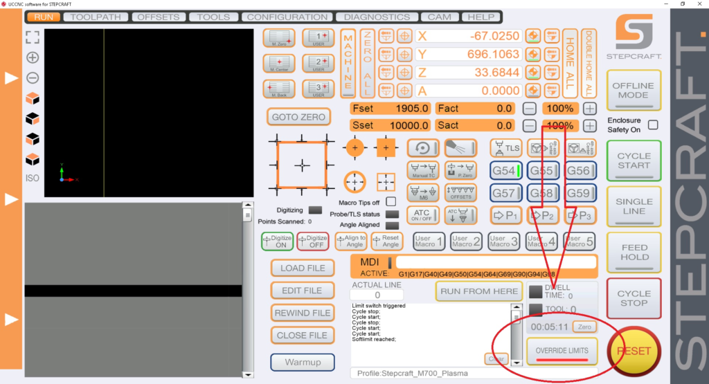
The “Override Limits” button is only to allow you to reset and jog the machine off any limit switch that may currently be engaged. Once the limit switch is disengaged, the “Override Limits” button will no longer flash red and you can home the machine. Another method to clear the switch is to engage your physical E-Stop button, which will cut power to the motors and allow you to turn the lead screws by hand to physically disengage the limit switch. For example, if your Z-Axis is on a switch and is all the way up, you can turn the screw about 1-2 turns until it is no longer activating the switch.
You can tell if a limit switch is currently active in your diagnostics screen in UCCNC. Below is an example of a machine with a limit switch currently active (green).
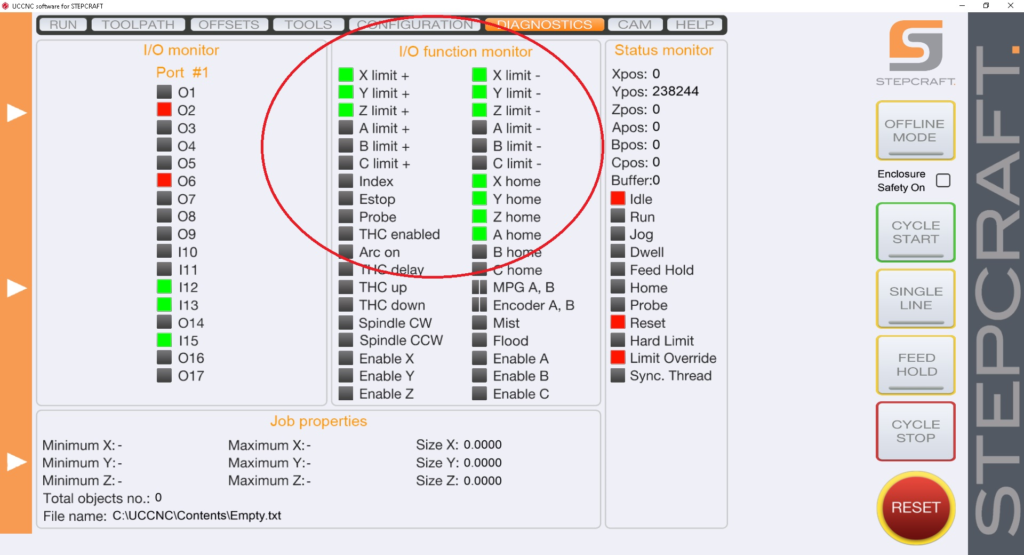
Note that the X, Y and Z limit switches are all on the same circuit, so when one is active all will show in UCCNC as active. This does NOT mean all three are active.
When you press E-Stop or power off your machine, it is possible that the Z axis can lower under its own weight towards the machine bed. This is most common on Q-Series machines with the ATC-2200 spindle and on M-Series machines that are equipped with ball screws.
Why does it happen? The ball screw system on the M and Q machines was designed for very smooth operation to allow the Z motor to be very responsive and provide excellent resolution. There is very little friction in the Z axis assembly on a ball screw machine. Because of this, the weight of the spindle can naturally cause the Z-axis to lower under its own weight when the Z-axis motor is not energized.
How do I resolve this? On the M-Series machines, there really is no direct resolution for this. You should make common practice on any CNC system to home all axes when you power the machine on or before you start using your machine on a given day. This way you can always be sure all your axes’ positions are recognized by the software and this is the best way to ensure that you have no issues with your Z height during your jobs.
Additionally, you should make sure you remove the tool holder (on Automatic Tool Changer spindles) before you power the machine down or remove the end mill from non-ATC spindles. Additionally, you can place something to support the Z Axis under it, such as a block of wood to prevent it from falling all the way to the table.
On the Q-Series machines, we have a solution that can resolve this issue as well as increase the performance of your Z axis during rapid Z operations such as when 3D carving. Please contact support@stepcraft.us for more info on this. Outside of this, the same applies to the Q as with the M, you should make it a common practice to home all your axes when you power on the machine or at the start of your work day.
On average you will see 125-150 hours of use on your MM-1000 DI spindle before you start to see signs that it is time to change them.
These signs can include:
sign 1
sign 2
You can order a replacement set from our website HERE.
If an error has occurred or your system has an obstruction causing the Semi-Closed Loop System to trigger, it will activate the E-Stop mode on the machine. When this happens the first thing you need to do is take note of the line number that you are at in the G-Code window on the lower left part of the UCCNC screen. Write it down or take a photo with your cell phone.
To reset this, you press the Red reset button on the UCCNC screen and then press HOME ALL. This will reset each axis so that everything is back in sync with UCCNC. From that point, you can use the START FROM HERE button and restart the job from right where you left off.
You can view this video on how to use the START FROM HERE button:
Laser Cutter/Engraver Questions
Yes, since it is essentially burning through the workpiece, some fumes will be produced. However, the system includes a built in exhaust extraction system with a fine particle filter to reduce the breathable fumes. It is recommended that you connect the output of the exhaust system to the outside of your work environment using flexible hose or PVC pipe (sold separately). This will ensure that the fumes are exhausted outside and not within the room your are working in.
Will the milling and laser tools work on other metals besides aluminum?
Yes, they will also machine brass and copper. STEPCRAFT machines are only designed for machining of non-ferrous metals. So you can not mill steel, stainless steel, etc.
Also note that the laser will NOT cut metals. you can use it to engrave but it will NOT cut!
Why my laser positioning light is not visible?
- Turn the power key switch to the ON position.
- Move the laser head approx. 20mm above work piece to focus positioning laser beam clearly.
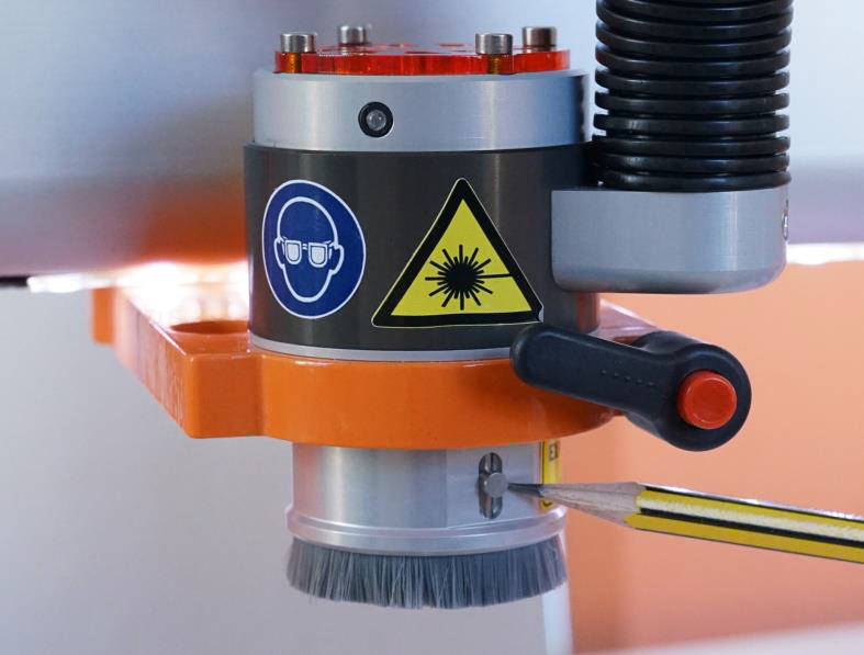
- To enable the positioning light, move the zero point sensor to the middle position and the light should turn on.
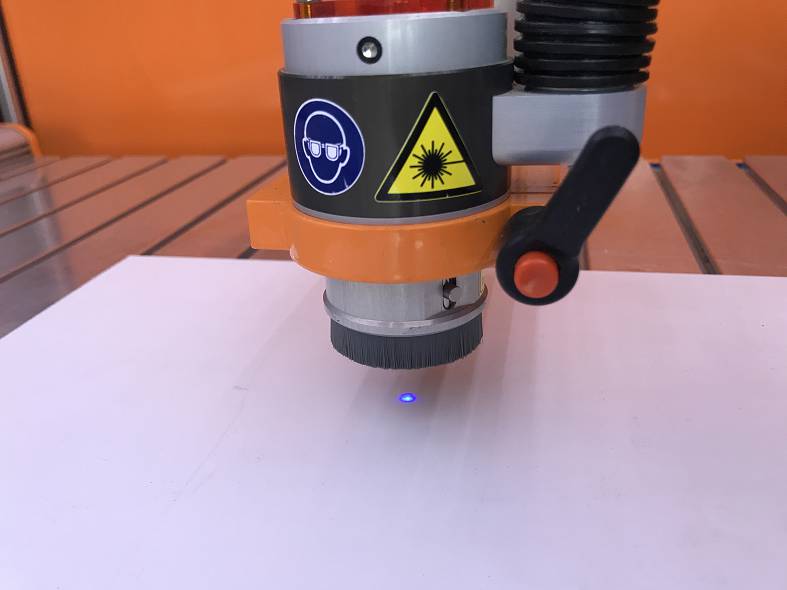
The positioning light is a class 2 laser with far less power (comparable to a laser pointer).
If your laser positioning guide wont turn on after following this procedure please contact our support team and they can guide you on how to fix this issue.
We have a special post processor that you need to use for the laser. You can download that file [here]
You need to place the file in the correct folder in your Vectric Program.
Do do this, open your program (V Carve, Cut 2D, etc)
In the FILE Menu, select OPEN APPLICATION DATA FOLDER

Look for a “PostP” or “My_PostP” folder

Copy the laser post processor file (downloaded above) Into both of these folders.
NOTE: if you copy the file into the My_PostP folder then when you open your Vectric Program, only the post processors in this folder will show. So I always recommend copying the post processors for my CNC into this folder so when you go to create a G Code file, you will not have to scan though a ton of files for other machines. If you do not want to use the My_PostP folder then simply copy the above Laser profile into the PostP folder and you will see it in the list of post processors.
ALSO, you will need to restart the program for the post processor to be visible in the list
The STEPCRAFT CNC comes with UCCNC machine control software, which also has a plug in that will transform a bitmap image into G Code for use with the Laser so you can laser engrave a photo or other bitmap image. However, if you wish to use the laser to cut projects out, then you need a CAM program like Vectric Cut 2D or V Carve to make the tool path for the laser to follow and then output the G Code for UCCNC to read.
To summarize:
For photos/bitmap engraving – No, you don’t need additional software
For cutting – Yes, you need a CAM program like Vectric Cut 2D/V Carve
The laser is 2 watts. This is a different type of laser than the more common CO2 laser machines. CO2 Lasers tend to be more powerful, but also larger and consume more power. CO2 lasers need to be fully enclosed because the laser is generated from a large glass laser tube that is fixed on the back of the machine. The beam is then directed via mirrors to the laser head where it is focused and sent to cut/engrave the material. The laser tubes on these machines get very hot and require external water cooling.
The STEPCRAFT laser is a solid state design which uses a laser diode (blue beam) that runs through a focusing lens and sent to the work material. While a 2 Watt laser does not sound as impressive as a 50 or 100 watt CO2, it is still surprisingly functional with the capability to cut through thinner materials (1/8″ or less wood and plastic) as well as a wide variety of engraving tasks. The STEPCRAFT CNC machine can not use a CO2 laser design because it is an open gantry machine and bouncing a laser beam around would be very dangerous. The Laser attachment will give you a lot of flexibility at a small fraction of the cost. The laser diode is contained right in the laser head and there are a lot of safety measures that have been designed into the product to ensure that you can have maximum flexibility on a CNC router.
Does the Laser DL445 use the same port on the STEPCRAFT as the 3D Printer and HF500 spindle?
Yes, they both use the same serial port on the back of the machine. You would need to disconnect the cable and reconnect the attachment that you wish to use. STEPCRAFT also offers a Switchbox which allows you to connect everything and simply turn the dial to select the attachment you wish to use. This is very handy if you are constantly changing attachments.
Can I engrave a photograph into a piece of wood?
Yes, you can use Vectric’s PhotoVCarve program, which allows you to create an engraving tool path for photos.
Additionally, you can use the new Laser Engraving Head DL445 which can laser engrave your photos into a variety of materials.
Are all of the machines capable of using the spindle, laser and 4th axis?
Yes, you can use all of these attachments on each of the machines. However the small size of the STEPCRAFT-1/210 might make it tough to use the 4th axis with longer work pieces. Additionally, the 210 has a limited 3″ Z height, which does not leave a lot of vertical travel and will limit the diameter of material that you can use on the machine. Additionally you really need a T-slot when using the 4th Axis so you can adjust the tail stock for the length of the work material and the 210 is the only machine that does not have a T-Slot option.
Maintenance
Z-Axis Alignment for STEPCRAFT D.Series Machines
The following videos will walk you through a typical Z-Axis Alignment…
Here is a video showing you how to do the cleaning and greasing procedure
An Example of an Aligned Stepcraft Machine
How to strength-test your Stepcraft CNC
Homing Each Axis
Speed Test
Alignment-z-axis
Z Axis Alignment – Disassembling the Z Axis
Z Axis Alignment – Setting the Z Axis Rollers
Z Axis Alignment – Lead Screw Nut Alignment
Z Axis Alignment – Inspecting Your Z Axis Stepper Motor
Z Axis Alignment – Reassembling Your Z Axis
Z Axis Alignment – Final Alignment and Testing
Y-Axis Alignment for STEPCRAFT D.Series Machines
Aligning your Y-Axis becomes much easier with our Y-Axis alignment support videos…
An Example of an Aligned Stepcraft Machine
How to strength-test your Stepcraft CNC
Homing Each Axis
Speed Test
Alignment-y-axis
Y Axis Alignment – Disassembling the Y Axis
Y Axis Alignment – Setting your Roller Tension
Y Axis Alignment – Aligning your Lead Screw Nut
Y Axis Alignment – Installing the Front Plate
Y Axis Alignment – Motion System Installation
Y Axis Alignment – Drive Belt Spacing and Installation
Y Axis Alignment – Checking Your Connections
Y Axis Alignment – Final Adjustment and Testing
Y Axis Alignment – Aligning Y manually
X-Axis Alignment for STEPCRAFT D.Series Machines
The following support videos will help walk you through aligning your X-Axis on a STEPCRAFT D.Series machine …
Here is a video showing you how to do the cleaning and greasing procedure
An Example of an Aligned Stepcraft Machine
How to strength-test your Stepcraft CNC
Homing Each Axis
Speed Test
Alignment-x-axis
X Axis Alignment – Disassembling the X Axis
X Axis Alignment – Setting the X Axis Rollers
X Axis Alignment – X Axis Lead Screw Nut Alignment
X Axis Alignment – Inspecting the X Axis Stepper Motor
X Axis Alignment – Reassembling the X Axis
X Axis Alignment – Final Adjustment and Testing
Why is My UCR201 Jog Pendant Not Showing Up In UCCNC?
The UCR201 Jog Pendant requires the user to enable the plugin in the configuration window in UCCNC. If you are running version 1.2037 of UCCNC, you may find that the Jog Pendant does not show up in the configuration window. If this is the case, you simply need to update UCCNC to a newer version which can be found below…
UCCNC Version 1.2049 – http://www.cncdrive.com/UCCNC/download_UCCNC.php
After downloading and installing version 1.2049 of UCCNC, the Jog Pendant should now be visible in the configuration window and you can proceed with the rest of the setup!
How come my circles are not perfectly round?
When you are machining circles on a CNC and your circles are not coming out perfectly round, it is commonly caused because there is some backlash developing on the machine. Backlash is a tiny amount of play that appears over time and is noticed when a drive changes direction.

When running in a positive direction, the gears/lead screw are engaged with the lead screw nut on the gantry, but when the stepper motor reverses direction there is a tiny space between the lead screw and the lead screw nut that has to be made up before there is positive engagement in that direction. After many, many hours of use or if your machine is not properly maintained and lubricated, then this backlash can develop.
If this is happening to you, please download this document: Stepcraft UCCNC Backlash Compensation.
This will show you how to setup backlash compensation in UCCNC so that you can “dial” out any backlash and go back to having perfect circles again.
What type of warranty does STEPCRAFT offer?
STEPCRAFT offers a full two-year warranty on all STEPCRAFT brand products and accessories.
The full outline of what is covered is available on the following link: https://stepcraft.us/warranty/
Fortunately there are not a lot of things that will break on the STEPCRAFT CNC, however from time to time, depending on how well you maintain the machine, you might have a part or two wear out and need to be replaced. When this happens, simply call or email our support department and they will take care of sending you a replacement part right away. There is a full two year warranty for all STEPCRAFT machines. If you need assistance replacing the part, STEPCRAFT’s support department can walk you through it on the phone, send you a how-to video or arrange a video conference call to help you though the process.
In extreme cases, where a customer has a machine that has not been assembled properly and needs support’s direct assistance, you can send it back to STEPCRAFT and the support team will fix/adjust, test, repackage and send back to you. This is a very rare scenario as 99% of the problems can be resolved quickly over the phone.
Understanding the Homing Procedure
Whenever you open UCCNC, the very first movement you should make with your machine is “Home All”. On a STEPCRAFT, the homing procedure begins with the Z-Axis, then the X-Axis and finally the Y-Axis. Each axis will run towards its limit switch until it engages the switch, then will run the opposite way until the switch disengages. Once all three axis have hit their limit switch, your machine is now ready to travel the full length of each axis!
This is known as a reference movement for the machine. Without this reference movement, the machine has no idea where it is along its axis and may not travel the full length back and forth. If your machine is stopping short of the full length of travel and you aren’t noticing any binding, make sure to “Home All” and try running again.
One important thing to note is that if any axis ever travels in the opposite direction of its limit switch when homing, check to make sure a limit switch is not engaged somewhere on the machine. All of the limit switches are on the same circuit, so if you tried to home your machine and the Y-Axis limit switch was pressed, the Z-Axis would travel in the OPPOSITE direction. This happens because the machine is going through the stage of homing when it backs away from the switch until it disengages. Because the Y-Axis switch was pressed, the Z-Axis will infinitely try to move away but it will never disengage.
My machine is in reset mode and I can not get it to reset, how can I fix this?
If your machine will not come out of reset mode, there are three things to check:
- Make sure that UCCNC is not running in Demo Mode. If UCCNC is running in demo mode, the software will not reset.
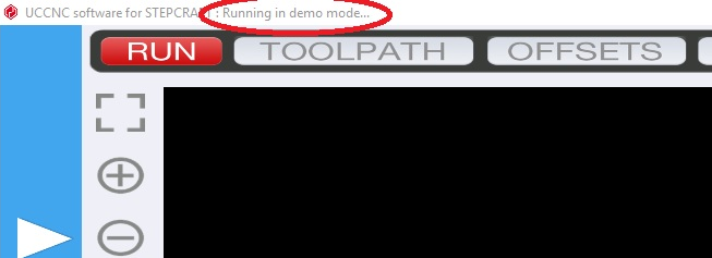
- Ensure that the emergency stop button is not press in on the front of the machine. You can disengage it by simply twisting it to the right slightly and it should pop out. If it is already out, then you can move on to #2.
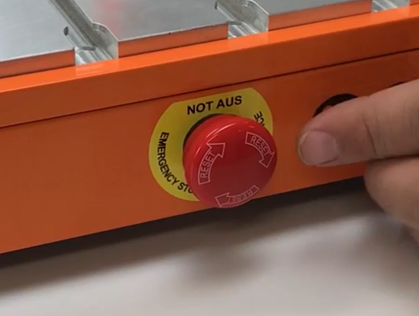
- Check the Y Axis limit switch wires on the back of the machine. Sometimes these wires can be accidentally knocked out and become disconnected. Be sure both wires are plugged in correctly.

- Click on the DIAGNOSTICS tab in UCCNC. Check to see if any of the limit switch lights are on in the I/O Function Monitor. (Please see the video below starting at 1:36)
On average you will see 125-150 hours of use on your MM-1000 DI spindle before you start to see signs that it is time to change them.
These signs can include:
sign 1
sign 2
You can order a replacement set from our website HERE.
How do I tram my Stepcraft CNC system?
The process of tramming your CNC system is an easy, but critical step to getting the most accurate results. By tramming your Z axis, you are insuring that the spindle will not be tilted to one side or the other, creating an unwanted angle to any milled areas. Included below is a short PDF covering the basic procedure of tramming your Stepcraft CNC system. The same concept can be done using a dial indicator or machinist’s square for even greater accuracy.
How do I Test a Faulty Stepper Motor?
When troubleshooting a faulty stepper motor, it is important to be weary of incorrect or shorted wiring. While inspecting your connections and wires may be required, there is a simple process that can save you some time and effort when testing your system’s steppers. Included below is a short PDF that covers the signs of a damaged or shorting stepper motor, and how to quickly diagnose the issue.
How Do I Level My Heated Bed for the 3D Printer?
The following video will show you how to level your heated bed for your 3D printer…
How do I connect my Remote Switchable Power Controller?
To connect your remote switchable power controller system, follow the diagram below…
How come my STEPCRAFT CNC kit did not come with lubricant?
There is a very good chance that your kit DID come with lubricant but you skipped past it in the box. The white container for the lubricant blends well with the white styrofoam from the kit dividers. There is a round pocket that is specifically designed to hold the lubricant container. Please look for this. If you still can not find it, then email support@stepcraft.us
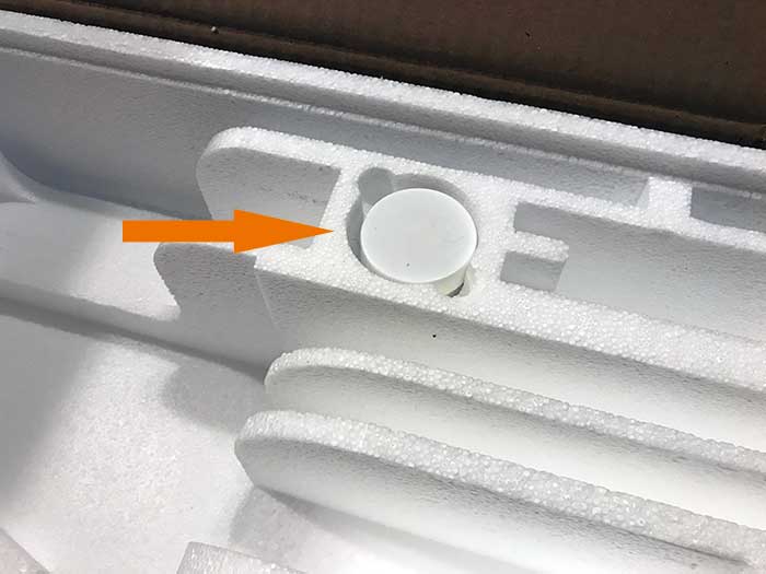
How Can I Calibrate My Tool Length Sensor?
If you find that your tool length sensor (TLS) is functioning properly, but not touching the very top of your material, you may need to preform a quick calibration. This ensures that the tool length sensor is accurate and reliable. The following video will walk you through the simple TLS calibration…
If you have your feeds and speeds correct, then the HF-500 should run for a very long time without overheating. There is an internal air cooling system build into the unit that will keep it running at optimal temperatures. But If you over stress the spindle, you can cause it to run hotter. The key is to ensure that you are not moving the bit through the material too fast and that you are not forcing the bit/spindle to remove too much material per pass. If the spindle is too hot to touch, then you are doing something wrong with your feed rate or depth per pass. You should always be able to touch the spindle and it should feel warm. If you can’t keep your hand on it for more than 15 seconds, then you need to look at your setup to ensure that you do not cause damage to the spindle.
No, you do not need to cover it. If you use an Exhaust Adapter or Dust collector, it will greatly minimize the dust that is generated from the tool making contact with the workpiece. STEPCRAFT sells enclosures that you can place the machine inside of which will prevent dust and debris from getting into the room. It will also help reduce the noice of the machine during operation. Regardless, there will always be some dust that gets on the machine when running. Even fine particles of wood dust will get airborne and can stick to the machine. That is why it is important to clean the machine daily and be sure to clean the tracks and lead screws every 20 hours of use and reapply grease.
Does STEPCRAFT have an online forum?
Yes, it is located on our German website at https://www.stepcraft-systems.com/en/service-and-support/stepcraft-forum-uk
There is also a Facebook group called the STEPCRAFT Crafter’s Club that is very active as well. You can visit that at www.stepcraftcraftersclub.com
Yes, end mills can be resharpened, however you need a special sharpening grinder in order to do this properly. Sharpening bits makes more sense with larger diameter end mills that are very expensive. If you are paying to sharpen your bits then it does not make good financial sense to sharpen smaller bits (1/8″, 1/4″ or smaller). The smaller the diameter of the bit, the more difficult it will be to sharpen it as well. Many bits that you will use on a small CNC router are going to cost less than $40 and good quality carbide bits will last you a very long time, especially considering the workloads derived from smaller CNC systems.
As an example, if I have a 1/4″ end mill that I have used for a year and paid $29 for it, I would simply throw it away and buy another before I would spend $20 to have it sharpened.
Project Design
Why is my project coming out incredibly small?
If your project is coming out incredibly small in UCCNC (e.g. 1/10th the size designed) you are most likely using the incorrect post processor. Every post processor used with a STEPCRAFT machine should end in (mm). This is because UCCNC will only accept millimeters as a parameter! Even if your project is designed entirely in inches, the (mm) post processors will automatically do the conversion from inch to mm for UCCNC to properly interpret. This means that you can design in inches, millimeters or anything you choose, and the post processor will always do the proper conversions for you. It is a very common mistake to select the (inch) post processor when working in inches. This will NOT do the proper conversion and UCCNC will interpret every inch measurement as a millimeter measurement. This is why the project, when saved with the incorrect (inch) post processor, will come out very small.
Drawing intricate designs in 3D is an art form unto itself and many people would prefer to buy or download file rather than trying to lead how to design it from scratch. Thankfully there are a few resources online that you can turn to in order to locate 3D files of military emblems, logos and designs.
www.cncmilitaryemblems.com – This site has many military emblems that are already designed in 3D can can be easily 3D Printed or CNC carved. The pricing is very reasonable when you consider how much time it would take to learn how to do this.
www.designandmake.com – This website has a lot of 3D designs that you can buy. There are some military ones that you can assemble into various models for specific designs. You can buy files individually or as a set.
![]()
www.thingiverse.com – Thingiverse has been around for a while and is basically a huge index of just about anything you can imagine. You will find some military designs and emblems on there by doing some simple searches. The best part about this site is that everything is free to download. Keep in mind that you do not have the right to sell the designs you download, but you can use them for personal needs. If you are working on a commercial project you should reach out to the person who designed the file and arrange to obtain rights to resell.
If you know of any other websites, please email info@stepcraft.us so we can add them to this list
The importing of images for use and processing with the STEPCRAFT CNC is purely dependent on the CAM software that you are using. For example, Vectric Cut 2D and V Carve both allow the importing of images in the following formats: .bmp, .jpg, .gif, .tif, .tiff, .png and .jpeg. You can not import native files from Pagemaker, Word, etc., only common bitmap formats.
If you have an image in another format or from another program, you can always import them into a graphics program like GIMP or Photoshop and then output them from there.
This is a question that can be answered in many ways.
Use A Premade Design
The easiest way to get a project made on the CNC is to buy a design that is already done for you. You can find many for free on the internet, but a few VERY good commercial options for 2D and 3D designs are:
- www.makecnc.com – Excellent selection of puzzles and other creative projects.
- www.designandmake.com – Very high quality 3D projects that can be reworked into hundreds of different possibilities.
- www.thingiverse.com – large selection of free 3D designs. Most are for 3D printing but many will work with a CNC as well.
- https://woodgears.ca/gear_cutting/template.html – Gear designer
- http://www.vectric.com/cool-stuff/projects.html – 2D and 3D high quality project files
- www.cnccraze.com – many project files
Bitmap Image Trace
Another option that is no as easy as just buying a file or downloading something that has been already designed, but is still easier than designing something from scratch, is to import an image or logo (i.e. from Google Images) and use the Image Trace feature in Vectric to create a vector from the bitmap image. Once it has been converted into a vector, you can assign tool paths to it and proceed to cut out on your CNC.
Another way to convert your bitmap images to vectors is to use the site (or software) https://vectormagic.com/. The online version of their program works very well and returns a vector that has excellent quality.
The following video shows you how to use Vectric’s Image Trace feature
Design Your Own
Sometimes you can not get exactly what you are looking to create from an online source that is pre-made, so you must turn to making your own design. This is not as scary as it sounds, especially if you are looking to cut out simple things like letters, signs, etc. The CAD (or design) part of Vectric programs make this easy. Cut 2D and V Carve have a design component to their software and you can quickly and easily design many different projects and then switch to the CAM part of the program to create the tool paths and output the G Code to the CNC.
You can also create vector designs with programs like Corel Draw and Adobe Illustrator, or if you need something designed to very specific dimensions, you can use a CAD program like Fusion 360 or Sketchup.
Hire Someone To Design For You
There are many outsourcing websites on the internet where people are looking for design work. You will be find many very talented people from all around the world and many (depending on the country) are willing to work for very reasonable rates.
www.upwork.com is one site where you will be able to post your job and have people bid on the project. You can read up on the applicant, discuss specifics and finally hire the person who best meets your needs.
You can go on websites like www.cnczone.com or the Facebook Group CNC Router Tips and put a post up with what you are looking to have designed and more often than not, you find people who are willing to do your design for a small fee (if not for free)
CNC Manufacturer
If all else fails, then contact the manufacturer of your CNC machine and ask them if they can help with the design or if they know anyone who you could contact.
YouTube is also a good source to find how-to videos that can show you how to make your designs or how to use various software programs.
Can you scan your own design and create a tool path to cut the object out on a CNC (Image Tracing)?
Vectric software, such as Cut 2D and VCarve have the ability for you to import a bitmap image and then use a function called “Image Trace” to create a vector around the image. You can then adjust and modify the vector to your liking. From there you can select the vector(s) and create a tool path for the CNC machine to cut around. You can also vary the depth of the cut to meet your specific needs.
The following video show you how to do this:
Are there any specific 3D Scanners that work best with STEPCRAFT, or any other CNC?
Honestly, No. Most 3D scanners are capable of generating and saving files in common 3D file format. That is really all that is required for STEPCRAFT. The resolution will vary, though, from scanner to scanner and typically the more expensive they are, the better the scan resolution:
Here is a good article with a list of the top 11 3D scanners for 2017: https://pinshape.com/blog/the-11-best-3d-scanners-on-the-market/
RMC 100 Wireless Controller
Why is My UCR201 Jog Pendant Not Showing Up In UCCNC?
The UCR201 Jog Pendant requires the user to enable the plugin in the configuration window in UCCNC. If you are running version 1.2037 of UCCNC, you may find that the Jog Pendant does not show up in the configuration window. If this is the case, you simply need to update UCCNC to a newer version which can be found below…
UCCNC Version 1.2049 – http://www.cncdrive.com/UCCNC/download_UCCNC.php
After downloading and installing version 1.2049 of UCCNC, the Jog Pendant should now be visible in the configuration window and you can proceed with the rest of the setup!
What is “MPG” on the STEPCRAFT RMC 100 Wireless Controller?
The term “MPG” stands for Manual Pulse Generator and is basically and electronic hand wheel. Selecting “MPG Mode” will allow you to rotate the wheel and move the axis on the machine in steps based on the indents in the wheel. This is a great way to move the spindle around, specifically when setting the starting position for each job.
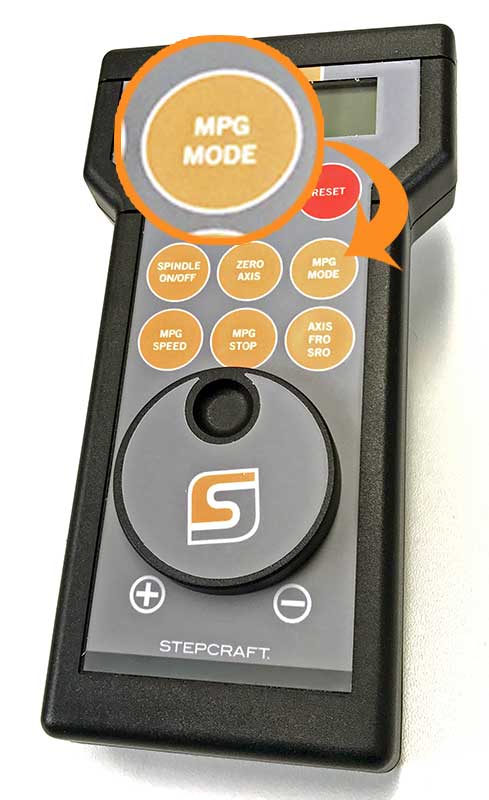
Shipping Questions
Pre-Assemble machines are BUILT TO ORDER. Typical delivery times for a pre-built machine is up to 30 days.
*We typically ship KIT machines within 14 days of purchase.
For USA, CANADA and MEXICO, Please call 203-556-1856 and select ‘support’ during normal business hours (M-F 9am to 5pm) or email support@stepcraft.us anytime day or night and someone will take care of you right away.
If you purchases your system from another country, please contact that dealer that you purchased your system from, or contact www.stepcraft-systems.com (the German headquarters) and someone will be able to help you
If I am from the USA, Canada or Mexico, does my machine get shipped from the Germany Headquarters?
No, Your order will ship from Torrington, Connecticut. Additionally, all post-sales support will also be done from our Torrington, CT office.
Software Troubleshooting
Why won’t the UCCNC installer complete when running the Stepcraft Multi-installer?
The most common cause that prevents the UCCNC installation from completing is due to the lack of Microsoft’s .NET Framework being installed. To do so, simply navigate to your Control Panel and select Programs. From there select the “Turn Windows Features on and off” option. Check the box for Microsoft .NET 3.5. Once your .NET framework is installed, continue with a fresh installation of UCCNC using the Stepcraft Multi-installer provided with your Stepcraft CNC system.
Why my 3D printer head (PH40) goes into Stand-By mode while working
The printers are going into standby and eventually shutting off because they are not receiving the correct signal from UCCNC that the machine is running. This is a very simple fix outlined below.
1.) Define pin outs in UCCNC –> CONFIGURATION –> I/O SETUP. On the left hand side you have “Current hi/low”. Those two pins should read “16” and “1”.
2.) Define pin outs in UCCNC –> AXIS SETUP –> SPINDLE. Bottom Left you have “M3 relay pin”. Change those values to “0” and “0” and uncheck the “spindle relay output enabled” if it is checked.
The most common cause for UCCNC running sluggish or slow, to the point where it is almost unusable, is because Windows had recently automatically installed an update in the background. This is most common when using Windows 10. CNC Drive, the makers of UCCNC software are very good with addressing these issues, however sometimes they have to wait until they even know there is an issue, which is usually when users notice the problem and contact CNCDrive or post online. If this happens to you before a UCCCNC update is available, then the fix is to uninstall the most recent Windows update (or updates). The following video shows you how to do this.
If this video still does not correct the problem, please email our support department at support@stepcraft.us
Why is the Yellow dot not in the location I set on my work piece in UCCNC?
In the live display window in UCCNC it shows you your project file as well as the location of the tool in real time. The tool is represented by a Yellow Dot on the screen. If you setup a job with the XY datum in the center of your job, then Yellow dot should be in the center of the screen in that window before you start running the job.
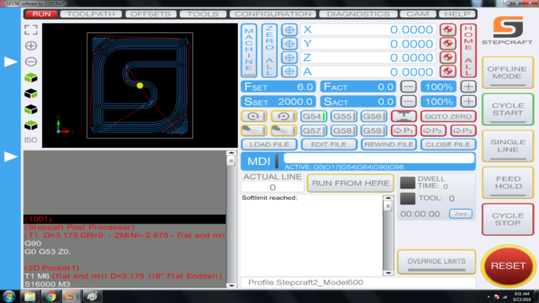
If the dot is NOT in the where you set it in your CAD/CAM file, then it is most likely because you did not ZERO X AND Y once you positioned the end mill (Spindle) at the starting location. Please use the following steps when you setup a job to ensure that your yellow dot is always where you want it before you run a job:
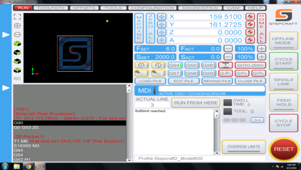
To ensure that your job is always setup properly, please follow these steps:
- Load your work piece onto the CNC and secure it
- Home your CNC machine (Press Home All on UCCNC)
- Manually move the end mill (spindle) to the location that you want to start the job on your work piece
- PRESS THE HOME BUTTON FOR Y AND X – this will reset the digital read out (DRO) to 0.00 for each.
- Load your GCode file – when you do you should notice that the yellow dot is where you set it up in your CAM file (lower left, center, etc)
- Set your Z Zero manually by lowering it to touch the material surface or machine bed (to match how your setup your CAM file) OR use a Tool Length Sensor
- Run your job!
When you home your machine, if the Z axis moves down towards the bed, it means you have a limit switch triggered somewhere on your machine and you have used the “Override Limits” button to reset and move the machine. If you try to Home the machine with the “Override Limits” button active, the Z-Axis will move straight down until it eventually crashes into the bed.
The “Override Limits” button is only to allow you to reset and jog the machine off any limit switch that may currently be engaged. Once the limit switch is disengaged, the “Override Limits” button will no longer flash red and you can home the machine. Another method to clear the switch is to engage your physical E-Stop button, which will cut power to the motors and allow you to turn the lead screws by hand to physically disengage the limit switch. For example, if your Z-Axis is on a switch and is all the way up, you can turn the screw about 1-2 turns until it is no longer activating the switch.
You can tell if a limit switch is currently active in your diagnostics screen in UCCNC. Below is an example of a machine with a limit switch currently active (green).
Note that the X, Y and Z limit switches are all on the same circuit, so when one is active all will show in UCCNC as active. This does NOT mean all three are active.
How come my circles are not perfectly round?
When you are machining circles on a CNC and your circles are not coming out perfectly round, it is commonly caused because there is some backlash developing on the machine. Backlash is a tiny amount of play that appears over time and is noticed when a drive changes direction.
When running in a positive direction, the gears/lead screw are engaged with the lead screw nut on the gantry, but when the stepper motor reverses direction there is a tiny space between the lead screw and the lead screw nut that has to be made up before there is positive engagement in that direction. After many, many hours of use or if your machine is not properly maintained and lubricated, then this backlash can develop.
If this is happening to you, please download this document: Stepcraft UCCNC Backlash Compensation.
This will show you how to setup backlash compensation in UCCNC so that you can “dial” out any backlash and go back to having perfect circles again.
Where can I find the M31 Macro for the Tool Length Sensor?
The M31 Macro for the Tool Length Sensor is automatically installed when you use the STEPCRAFT Multi-Installer. The best way to make sure you are up to date with our latest profiles and macros is to download the STEPCRAFT Multi-Installer here. This installer will automatically install the most up to date profiles and macros.
If you find that after using the tool length sensor your end mill is slightly above or slightly digs into your material, you may need to preform a small adjustment to the M31 macro. To preform this adjustment, you can find the procedure here.
Where can I download UCCNC?
UCCNC is the machine control software that moves your STEPCRAFT machine and interprets G-Code. In order to use your STEPCRAFT machine, you will need the UCCNC software as well as the STEPCRAFT machine specific profiles. You can download and install both from the STEPCRAFT Multi-Installer that comes on your orange USB flash drive, or download here. STEPCRAFT will always have the latest compatible version of UCCNC included in the Multi-Installer. If you are looking for the newest released version of UCCNC, you can download here (note: UCCNC may release versions newer than those included on the STEPCRAFT Multi-Installer. These versions may not have been fully tested and may cause some bugs/issues with your machine. It is reccomended to use the version of UCCNC included on the STEPCRAFT Multi-Installer).
Where Can I Download the Stepcraft Multi-Installer?
The multi-Installer can be found on the orange USB flash drive sent with every D. series CNC system, or can be downloaded from the Dropbox link below.
Stepcraft D. Series Multi-Installer:
https://www.dropbox.com/s/vytptg88ahqbc8g/Stepcraft_Multi_Installer.exe?dl=0
What post processor do I use for Vectric programs (Aspire, VCarve, Cut 2d, Cut 3D, PhotoVCarve)?
NOTE: These post processors will work for BOTH UCCNC and WIN-PC NC
From the dropdown list in Vectric programs, you will look for the following
If you have an Automatic Tool Changer: Stepcraft UCCNC ATC Arcs (mm) (*.txt)

If you do not have an Automatic Tool Changer: Stepcraft UCCNC Arcs (mm) (*.txt)

If you have an older version of Vectric software and the STEPCRAFT post processors are NOT in the dropdown list, please use the following:
If you have an Automatic Tool Changer: Mach2/3 ATC Arcs (mm) (*.txt)
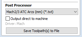
If you do not have an Automatic Tool Changer: Mach2/3 Arcs (mm) (*.txt)
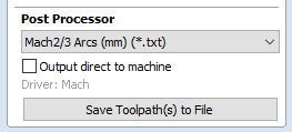
After the initial launch of the M-Series line of CNC machines, a change was made in our driver system causing us to need two versions of the profile for the M.1000 machine.
How do I know which one I need? If you purchased your machine BEFORE April 2022, then you need the M.1000 profile. If you purchased AFTER April 2022, then you need the M.1000T profile.
How do I get the profile? Please contact our support department at support@stepcraft.us and we can assist you to ensure you have the correct profile.
What is the difference between the two profiles? The main difference is in the assignment of steps-per-inch (or steps-per-mm) for the newer driver cards. This profile ensures that UCCNC is configured properly for your driver card.
Are there any issues with the pre-2022 machines or drivers? NO. There are no performance, reliability, or accuracy issues with the original drivers. It is merely a software configuration change that we had to make.
Sometimes when you start UCCNC you will get the “Select the motion controller device from the list” message box that pops up. This is either happening because your UC100 interface or USB cable is unplugged or the device driver did not properly install. This video will show you how to fix this.
If you are still have trouble after watching this video, please contact our support team at support@stepcraft.us.
What does “The current job workspace is out of the set software limits” error window mean?

This error happens when your design is larger than the allowable work area on the CNC machine. Every machine has its own specific software profile that you install with UCCNC. This software profile tells UCCNC what the available work area size is on your machine. The main reason for this is to protect your machine from crashing into itself if you run a job that is larger than the machine’s capabilities. Think of the “software limits” as invisible limit switches. When you load a job into UCCNC, it looks at the G-Code automatically and compares the XYZ dimensions of your file against the software profile to make sure that the job can fit on your machine. If the settings in your file are larger than the work area, then you will get this error window.
Sometimes, if your job is NOT larger than the work area size for your machine and you get this error, you can reposition your work piece so when you zero X and Y that you fall within the work area. For example. Say your machine has a work area limits that are set to 420 mm on Y and 300 mm on X and you are trying to run a job that is 380 mm long x 280 mm wide. This job should work with no problem, however if you have the work piece positioned more than 20mm from the left side of the machines work area limit or 40 mm away from the front of the machine, and you have zeroed UCCNC in that position, then you will get this error when you start the job because it adds the job size to the position where you have X and Y zeroed and if that number is greater than 420 on Y or 300 on X it triggers the error.
It is important to take into account your “safe Z height” when encountering this error. If your safe Z height causes the Z-Axis to travel past the limits of the machine you will get this error. This is very common when working with thicker materials or long end mills. You can adjust your safe Z height in two places…
1.) In your CAD/CAM program. If you are using Vectric it will be under “Material Setup”.
2.) In UCCNC –> CONFIGURATION –> GENERAL SETTINGS. About half way down on the right side you have your “Safe Z height (Units). You can lower this number for more room.
The two values do stack, so if you are still having trouble try lowering both.
Another common cause for the error is to verify where your XY Datum is located in your design file. Many times a job might have been set with a XY datum of the lower left corner but the operator sets the machine up as if the XY Datum is in the center. This will, in most cases, cause the error because that zero position added to the jobs work size will exceed the software limits of the profile in UCCNC.
On rare occasions when you click the UCCNC installer, it will seem like it is going to run but then nothing happens. In order for UCCNC to properly install, it requires the .Net 2.0 framework and some Windows 10 machines, it is turned off by default. You can turn this on easily by following this video.
If after watching this video, you are still having problems, please email our support team at support@stepcraft.us
Understanding the Homing Procedure
Whenever you open UCCNC, the very first movement you should make with your machine is “Home All”. On a STEPCRAFT, the homing procedure begins with the Z-Axis, then the X-Axis and finally the Y-Axis. Each axis will run towards its limit switch until it engages the switch, then will run the opposite way until the switch disengages. Once all three axis have hit their limit switch, your machine is now ready to travel the full length of each axis!
This is known as a reference movement for the machine. Without this reference movement, the machine has no idea where it is along its axis and may not travel the full length back and forth. If your machine is stopping short of the full length of travel and you aren’t noticing any binding, make sure to “Home All” and try running again.
One important thing to note is that if any axis ever travels in the opposite direction of its limit switch when homing, check to make sure a limit switch is not engaged somewhere on the machine. All of the limit switches are on the same circuit, so if you tried to home your machine and the Y-Axis limit switch was pressed, the Z-Axis would travel in the OPPOSITE direction. This happens because the machine is going through the stage of homing when it backs away from the switch until it disengages. Because the Y-Axis switch was pressed, the Z-Axis will infinitely try to move away but it will never disengage.
My machine is in reset mode and I can not get it to reset, how can I fix this?
If your machine will not come out of reset mode, there are three things to check:
- Make sure that UCCNC is not running in Demo Mode. If UCCNC is running in demo mode, the software will not reset.
- Ensure that the emergency stop button is not press in on the front of the machine. You can disengage it by simply twisting it to the right slightly and it should pop out. If it is already out, then you can move on to #2.
- Check the Y Axis limit switch wires on the back of the machine. Sometimes these wires can be accidentally knocked out and become disconnected. Be sure both wires are plugged in correctly.
- Click on the DIAGNOSTICS tab in UCCNC. Check to see if any of the limit switch lights are on in the I/O Function Monitor. (Please see the video below starting at 1:36)
If I use Solidworks CAM or Fusion 360 CAM, do I still need to use UCCNC or Mach 3?
The purpose of any CAM program is to take your design file and turn it into G-Code by assigning tool paths to your project and outputting it in a format that a CNC machine can understand.
That being said, you still need a method of controlling the CNC machine, which is where programs like Mach 3 and UCCNC come in. They are designed to connect to the CNC machine and the G-Code files that you create in your CAM program are loaded into Mach 3 or UCCNC to run the machine.
With any CNC router, you have three main steps to creating a project:
- Design your project in a CAD/Drawing program
- Use a CAM program to assign tools and tool paths to the project
- Use a machine control program to load the G-Code files and run the CNC machine.
How do I save/find my digitized 3D Touch Probe file?
If you are having trouble saving or finding your digitized file after scanning with the 3D touch probe, you may have to force Windows to save the file as a .txt file. To do this, either initially after the scan or after opening the file, save as and type your file name, followed by .txt and enclosed in quotes. For example…
“car.txt”
“model.txt”
This will force windows to save the file as a .txt, which can be easily recognized and opened.
If an error has occurred or your system has an obstruction causing the Semi-Closed Loop System to trigger, it will activate the E-Stop mode on the machine. When this happens the first thing you need to do is take note of the line number that you are at in the G-Code window on the lower left part of the UCCNC screen. Write it down or take a photo with your cell phone.
To reset this, you press the Red reset button on the UCCNC screen and then press HOME ALL. This will reset each axis so that everything is back in sync with UCCNC. From that point, you can use the START FROM HERE button and restart the job from right where you left off.
You can view this video on how to use the START FROM HERE button:
How do I Recover My UCCNC License File?
If you have misplaced or lost your UCCNC license key file, the process of recovering it is fast and easy. The serial number located on one side of your UC100 corresponds to your hard-coded license key, as shown below. Simply contact our support team and provide them with this serial number, and you will receive your recovered license file as an email attachment.

How can I reset my Stepcraft UCCNC installation?
Can’t seem to solve a strange bug or error? Can’t find a fix here? Mismatched or changed profile settings are a very common cause, but what if you cannot locate the setting that is giving you these issues?
A fresh installation will take care of making sure your profile settings match the default ones and make sure that you are not going in circles when troubleshooting UCCNC. This short video will walk you through each step required to not only remove any trace elements of your old installation, but also covers how to re-install your profiles to reduce downtime and get your machine back up and running.
Does the UCCNC installer contain a virus?!?
Some virus protection software companies have flagged the UCCNC installer as possibly containing a “trojan virus”. Rest assured, there is absolutly ZERO threat of a virus contained within the UCCNC installer. We are working diligently with the creators of UCCNC and companies such as Norton to have this flag removed so our customers can have a smooth installation process. For now, you may need to turn your virus protection off to install the UCCNC.exe file. You can immediately turn the software back on as soon as the program has been installed. We apologize for the inconvenience! If you have any questions or concerns, please feel free to give us a call directly at (203)556-1856.
Can I use Fusion 360 from Autodesk with my STEPCRAFT CNC?
Yes, you can use Fusion 360 with STEPCRAFT. There is a post-processor that you can download for the CAM portion of Fusion 360 by going to https://cam.autodesk.com/hsmposts?
Fusion 360 is a very powerful program that can greatly expand the capabilities of what you can do with a STEPCRAFT (or any CNC for that matter).
Can I use a Mac with a STEPCRAFT CNC?
Yes! While the UCCNC and Vectric Software both run on Windows platforms, you can use a MAC as long as you run Parallels software which allows you to install Windows on your Mac. You can not run UCCNC or Vectric natively on a Mac (without Parallels). If you use Fusion 360 for CAD/CAM, then you can install that natively as they have a Mac version of that software. However, UCCNC will still need Parallels with Windows.
NOTE: Since a Mac computer is typically much more expensive than a Windows system, and the fact that UCCNC does not need a powerful computer, we recommend using your Mac for the design work and then getting an inexpensive or refurbished computer (desktop or laptop) to use to run the CNC, since the area around the CNC can potentially have dust and chips that might get on or near the computer.
Spindles and Routers
Your spindles seem much smaller than larger CNC Routers’ 2.5Kv spindles, how can they do the job as well?
The spindle is proportional to the size of the CNC. A STEPCRAFT CNC with a 800W spindle will be able to do the same jobs as a large 4×8 foot machine with a 2.5Kv spindle, however, it will not be able to run as aggressively. So If you can run 60 mm/sec on a large industrial machine with a more powerful spindle, you can do the same job on a STEPCRAFT with an 800W spindle but you might only be able to run at 30 mm/sec. You will also have to take less material off per pass on the smaller machine than you can on the larger machine.
You also need to keep in mind that a good quality 2.5Kv water-cooled spindle can cost more than entire STEPCRAFT CNC system. It is really apples and oranges. If you are in the market for a machine for industrial or high production use, then you should be looking at a larger CNC with a more powerful spindle. However, if you are looking for a precision CNC that can do just about anything, but you would need to run less aggressively, then the STEPCRAFT would be more than enough machine.
No. We do not offer an attachment bracket for full size routers. Additionally, the weight of the router would be too heavy for our Z Axis motor to lift. We do have the ability to use trim routers like the Dewalt DW611 or other brands. These routers will provide more than enough power for any project that you would do with a STEPCRAFT CNC.
There is really not much comparison between the two. Both tools are similar only in that fact they both hold a router bit and can rotate it to cut material at high speeds. A router is a 110V consumer grade tool that is rated for intermittent use while a spindle is an industrial motor that has been manufactured to run all day long, day in and day out for exactly the purpose you want to purchase it for – CNC cutting. Spindles are more powerful (note that hp ratings between routers and spindles are not comparable) and will maintain their full torque down to much lower RPMs than a router. Spindles have precision bearings, which means less run-out and thus smoother and more accurate cutting. The bearings on a spindle also stand up to continuous use better than those of a router. Bearings in a heavily used router will need to be replaced every three-four months, while a similarly used spindle should be good for a few years between bearing replacements. A spindle is also much quieter in operation than a router.
That been said, if you don’t need a heavy cut and noise is not an issue, then a router is a safe choice. In production situations, we highly recommend a spindle. In addition, the full performance capabilities of our machines are fully realized with a spindle because a router will bog down in heavy cutting at higher cutting speeds.
In making a decision, the real dividing line between the two is on how you make your money. If your paycheck comes from someplace outside your shop, then buy whichever you feel you can afford. If your paycheck is generated inside your shop, and your living and reputation is on the line, you need the security and substantially higher cut quality that comes from a spindle.
What is the total usable Z height on the D-Series CNC?
The D-Series 420, 600 and 840 all have a max Z height of 140mm (5.51″). However this does not represent the maximum height of material you can process. From this height you need to subtract the spindle collet nut stick out as well as the length of the cutting tool you are using.
The following represents the spindle and spindle nut stick out you get on a D-Series machine with the HF-500 and MM-1000 spindles
HF-500: 31mm (1.22″)
MM-1000: 38.6mm (1.52″)
MM-1000 (with single spacer): 32.56mm (1.28″)
MM-1000 (with dual spacers): 26.34mm (1.04″)
- NOTE: This is the case with just about every CNC machine on the market, not just STEPCRAFT CNC. Most all CNC machines will have spindle and spindle nut/tool holder stick out that takes away from the usable Z height.
So if you take into consideration the MM-1000 with dual spacers, you would have a total Z height of 140mm (5.51″) minus 26.34mm (1.04″) leaving you with a new max Z height of 113.66mm (4.47″).
Now depending on what you intend to do, you can use this new value to plan your project. If you want to cut all the way through material, you would need to have a tool that is long enough, which you would further subtract from the new Z height value.
Example 1: New Z Value is 113.66mm (4.47″), if you divide that number in half, that would mean you can use a piece of material that is 56.83mm (2.23″) thick and the tool would have to stick out 56.83mm (2.23″) as well.
- NOTE: This would also mean that the cutting height of the tool would have to be a min of 56.83mm (2.23″) or you run the risk of rubbing the shank of the tool on the material.
Example 2: If you intend to only engrave on top of a piece of material, then your tool stick out can be much less. If you use an engraving blank that sticks out say 12mm from the bottom of the collet nut, then that means you can have a max material height of 101.66mm (4″).
- NOTE: please keep in mind you should also allow for a couple 2-3mm of Z height clearance for rapid, non-cutting moves on the CNC as well. So you would subtract another 2-3mm from the above numbers in a practical application.
TWO SIDED MACHINING – For thicker material
One way that you can increase your max material thickness that you can cut through is using double sided machining.
Example: You can take your new Z value of 113.66mm (4.47″) and divide that into thirds. This would mean you can have a material thickness of 75.33mm (2.96″), or two-thirds and using a cutter with a length of 38mm (1.49″) you can cut one side of the project and then flip it over and cut the other side – so you are using a shorter cutter to cut through a thicker material by cutting each side.
Example:
What is the difference between the Kress, HF-500, Dremel and Dewalt spindles?
We made a video to fully answer this question.
NOTE: The new HF500 spindles NO LONGER come with an air pump as we use sealed bearings and the pump is no longer required.
What is the collet range sizes that the HF-500 Spindle can accept?
The HF-500 can support up to 8mm ER11 collets. The most popular in North America are 1/8” and 1/4”, but they have collets that range from 1mm to 8mm that will work. The ER11 is an industry standard that determines the overall collet size. ER11, ER16, ER20, ER25 are all common sizes. But the HF 500 and our Tool Changer tool holders for the MM-1000 are both designed for the ER11.
What is a surfacing bit used for?
A surfacing bit typically has a larger than normal cutting diameter (1 to 3 inches) and are used to flatten or level uneven surfaces on your project material. They are also used to take the thickness of a material down to a final required size. For example, you might have a piece of rough cut lumber that measures 1 inch in thickness but you need it to be 3/4 inch thick. If you don’t have a surface planer in your shop then you can use a surfacing bit with a pocket tool path to plane the material down.
Another common use for surfacing bits is to clean up and level a spoil board. After continuous use your spoil board’s surface will have a lot of cuts in it and you might want to clean it up so it is perfectly smooth again. A surfacing bit is perfect for this, especially with machines where the spoil board is physically attached to the machine – you might want to prolong the use of it for as long as you can before replacing.
Leveling your spoil board is also important. If you are looking to engrave .005″ into a piece of metal and your bed is off by a couple thousandths from one side to the other or front to back, then the thickness of your engraved lines will vary. By using a surfacing bit, you will ensure that your spoil board is perfectly level in relation to your gantry which will result in a uniform engraving.
Note: Because of the larger diameter of a surfacing bit, it is important to note that you can not take as deep of passes or run as fast as you might with smaller end mills on most machines. Consult your machine’s manufacturer for assistance with proper speeds and feeds for surfacing bits.
The HF500 now comes with a new sealed bearing system which no longer requires the need for the air pump. The following note should have been included with your package.
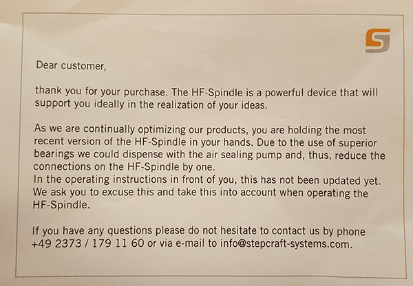
My Q-Series will turn on while pressing the green button, but will not stay energized.
Your E-Stop could be active. Check to make sure the E-Stop in the front face of your machine is not engaged. Also, the US 110 volt edition of Q-Series machine has an additional spindle safety circuit to check – Make sure your 110 volt plug from the back of the machine is connected to a live power source, or, your spindle safety override switch (located on the top of the machine) is engaged.


On average you will see 125-150 hours of use on your MM-1000 DI spindle before you start to see signs that it is time to change them.
These signs can include:
sign 1
sign 2
You can order a replacement set from our website HERE.
How do I tram my Stepcraft CNC system?
The process of tramming your CNC system is an easy, but critical step to getting the most accurate results. By tramming your Z axis, you are insuring that the spindle will not be tilted to one side or the other, creating an unwanted angle to any milled areas. Included below is a short PDF covering the basic procedure of tramming your Stepcraft CNC system. The same concept can be done using a dial indicator or machinist’s square for even greater accuracy.
How do I connect my Remote Switchable Power Controller?
To connect your remote switchable power controller system, follow the diagram below…
If you have your feeds and speeds correct, then the HF-500 should run for a very long time without overheating. There is an internal air cooling system build into the unit that will keep it running at optimal temperatures. But If you over stress the spindle, you can cause it to run hotter. The key is to ensure that you are not moving the bit through the material too fast and that you are not forcing the bit/spindle to remove too much material per pass. If the spindle is too hot to touch, then you are doing something wrong with your feed rate or depth per pass. You should always be able to touch the spindle and it should feel warm. If you can’t keep your hand on it for more than 15 seconds, then you need to look at your setup to ensure that you do not cause damage to the spindle.
Does the Laser DL445 use the same port on the STEPCRAFT as the 3D Printer and HF500 spindle?
Yes, they both use the same serial port on the back of the machine. You would need to disconnect the cable and reconnect the attachment that you wish to use. STEPCRAFT also offers a Switchbox which allows you to connect everything and simply turn the dial to select the attachment you wish to use. This is very handy if you are constantly changing attachments.
No, we do not have one at this time. However there are many universal ones on the internet as well as DIY models that you can make yourself.
No, you do not need to use different spindles. The main factor will be how fast the feed rate will be that you run and how much material you remove per pass.
If you with to run a light duty spindle like a Dremel 4000, you can run wood, plastics and metals just as well as if you were using a Kress 800W spindle. The only difference is that you will not be able to remove as much material and your feed rate will be slower the harder the material is.
Keep in mind that dedicated CNC spindles will have better quality bearings which will offer less runout and therefore a longer life span and higher accuracy. Using the Dremel example, this device is not meant for hours and hours of prolonged use, nor is it made to have lots of pressure side loading the main shaft. You will find that if you are not careful on the feed rate and pass depth that you will quickly wear out the bearings.
A router like the Dewalt DW611 will also cut all types of material, but as with the Dremel, the bearings are not as good as with a dedicated spindle so you can expect more runout with a router. The STEPCRAFT HF500 is a purpose built spindle that was designed to work with all types of materials and has an excellent bearing system that provides very little runout and a much higher accuracy.
The bottom line is that you can pretty much cut whatever you like with just about any spindle. You just need to be cautious on feed rates and pass depth.
Can I connect my HF-500/MM-1000 spindle and 3D printer to the STEPCRAFT at the same time?
Yes you can with the use of the of the STEPCRAFT System Attachment Switch Box. To use the Switch Box, you simply plug a serial cable from the Switch Box to the serial port on the CNC and then you plug the 3D Printer and the HF500 Spindle into the respective ports on the back of the box. Then you can just rotate the dial to select the attachment that you would like to use and mount that attachment into the tool holder on the STEPCRAFT.
Are all of the machines capable of using the spindle, laser and 4th axis?
Yes, you can use all of these attachments on each of the machines. However the small size of the STEPCRAFT-1/210 might make it tough to use the 4th axis with longer work pieces. Additionally, the 210 has a limited 3″ Z height, which does not leave a lot of vertical travel and will limit the diameter of material that you can use on the machine. Additionally you really need a T-slot when using the 4th Axis so you can adjust the tail stock for the length of the work material and the 210 is the only machine that does not have a T-Slot option.
STEPCRAFT Assembly Questions
Z-Axis Alignment for STEPCRAFT D.Series Machines
The following videos will walk you through a typical Z-Axis Alignment…
Here is a video showing you how to do the cleaning and greasing procedure
An Example of an Aligned Stepcraft Machine
How to strength-test your Stepcraft CNC
Homing Each Axis
Speed Test
Alignment-z-axis
Z Axis Alignment – Disassembling the Z Axis
Z Axis Alignment – Setting the Z Axis Rollers
Z Axis Alignment – Lead Screw Nut Alignment
Z Axis Alignment – Inspecting Your Z Axis Stepper Motor
Z Axis Alignment – Reassembling Your Z Axis
Z Axis Alignment – Final Alignment and Testing
Y-Axis Alignment for STEPCRAFT D.Series Machines
Aligning your Y-Axis becomes much easier with our Y-Axis alignment support videos…
An Example of an Aligned Stepcraft Machine
How to strength-test your Stepcraft CNC
Homing Each Axis
Speed Test
Alignment-y-axis
Y Axis Alignment – Disassembling the Y Axis
Y Axis Alignment – Setting your Roller Tension
Y Axis Alignment – Aligning your Lead Screw Nut
Y Axis Alignment – Installing the Front Plate
Y Axis Alignment – Motion System Installation
Y Axis Alignment – Drive Belt Spacing and Installation
Y Axis Alignment – Checking Your Connections
Y Axis Alignment – Final Adjustment and Testing
Y Axis Alignment – Aligning Y manually
X-Axis Alignment for STEPCRAFT D.Series Machines
The following support videos will help walk you through aligning your X-Axis on a STEPCRAFT D.Series machine …
Here is a video showing you how to do the cleaning and greasing procedure
An Example of an Aligned Stepcraft Machine
How to strength-test your Stepcraft CNC
Homing Each Axis
Speed Test
Alignment-x-axis
X Axis Alignment – Disassembling the X Axis
X Axis Alignment – Setting the X Axis Rollers
X Axis Alignment – X Axis Lead Screw Nut Alignment
X Axis Alignment – Inspecting the X Axis Stepper Motor
X Axis Alignment – Reassembling the X Axis
X Axis Alignment – Final Adjustment and Testing
Pre-Assemble machines are BUILT TO ORDER. Typical delivery times for a pre-built machine is up to 30 days.
*We typically ship KIT machines within 14 days of purchase.
Why is My UCR201 Jog Pendant Not Showing Up In UCCNC?
The UCR201 Jog Pendant requires the user to enable the plugin in the configuration window in UCCNC. If you are running version 1.2037 of UCCNC, you may find that the Jog Pendant does not show up in the configuration window. If this is the case, you simply need to update UCCNC to a newer version which can be found below…
UCCNC Version 1.2049 – http://www.cncdrive.com/UCCNC/download_UCCNC.php
After downloading and installing version 1.2049 of UCCNC, the Jog Pendant should now be visible in the configuration window and you can proceed with the rest of the setup!
Where do I attach the green ground cord on the Stepcraft D-Series machine?
The green ground cord is used to provide a way for any possible static that would build up on the machine to discharge back to earth ground. The ring terminal on the green ground cable that comes with your machine is attached to one of the screws from the control board mount on the bottom of the machine. Any of the screws will work just fine.
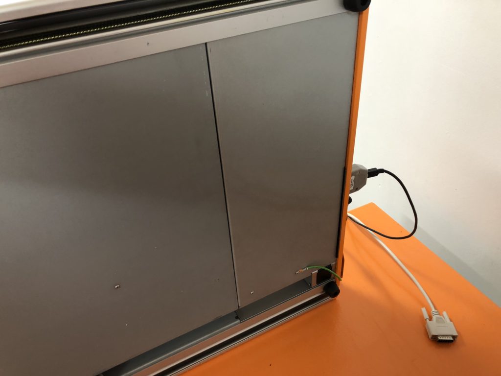
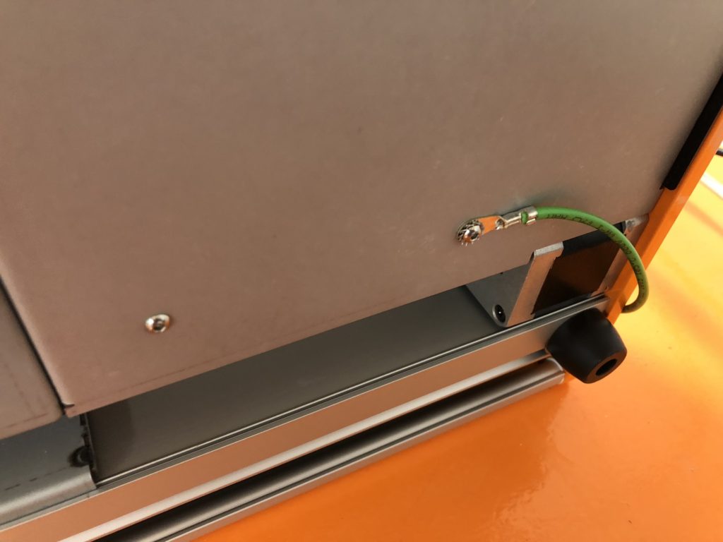
What tools are required to build a STEPCRAFT CNC machine?
We have a free video from our Assembly Course that explains it: http://www.stepcraftsupport.com/edu/lesson/tools-required/
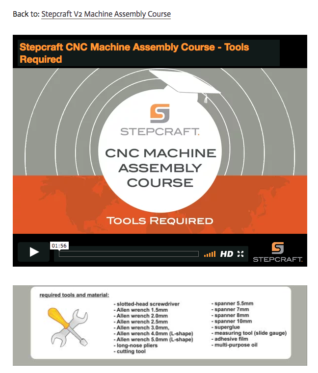
For USA, CANADA and MEXICO, Please call 203-556-1856 and select ‘support’ during normal business hours (M-F 9am to 5pm) or email support@stepcraft.us anytime day or night and someone will take care of you right away.
If you purchases your system from another country, please contact that dealer that you purchased your system from, or contact www.stepcraft-systems.com (the German headquarters) and someone will be able to help you
With well over 6500 STEPCRAFT systems sold around the world, there stands to reason that a small percentage of customer might have some trouble. The instructions are very well thought out for any level of builder, but still, you MUST follow them step by step. Additionally we produced a Assembly Training Course that is a video tutorial outlining every step in the manual. Between the manual and videos, the average customer should not have any trouble.
We find that many customers who you are reading about either do not have the skill set to understand basic assembly terminology or are skipping steps in the assembly process. Many times a quick call to our support team has the customer up and running quickly.
There are no special tools or skills required to assemble a STEPCRAFT kit, but if you are the type of person who “skims” through manuals and are not detail oriented when assembling something, then you might have the same issues that some people post about. While it is not a hard build, there are a few items that you must pay attention to due to the precise nature of the machine.
If you take your time and follow the steps in the videos and manual, you will not have any problems building your STEPCRAFT CNC.
On average it takes between 8-10 hours depending on your skill level. The kits are not hard to assemble and there are no special tools required. We also have an online video training course that walks you though every step of the assembly process.
How do I tram my Stepcraft CNC system?
The process of tramming your CNC system is an easy, but critical step to getting the most accurate results. By tramming your Z axis, you are insuring that the spindle will not be tilted to one side or the other, creating an unwanted angle to any milled areas. Included below is a short PDF covering the basic procedure of tramming your Stepcraft CNC system. The same concept can be done using a dial indicator or machinist’s square for even greater accuracy.
How do I Test a Faulty Stepper Motor?
When troubleshooting a faulty stepper motor, it is important to be weary of incorrect or shorted wiring. While inspecting your connections and wires may be required, there is a simple process that can save you some time and effort when testing your system’s steppers. Included below is a short PDF that covers the signs of a damaged or shorting stepper motor, and how to quickly diagnose the issue.
How do I connect my Remote Switchable Power Controller?
To connect your remote switchable power controller system, follow the diagram below…
How come my STEPCRAFT CNC kit did not come with lubricant?
There is a very good chance that your kit DID come with lubricant but you skipped past it in the box. The white container for the lubricant blends well with the white styrofoam from the kit dividers. There is a round pocket that is specifically designed to hold the lubricant container. Please look for this. If you still can not find it, then email support@stepcraft.us
Yes, ALL Machines and most attachments come with a printed manual. Some newer products or smaller attachments might only come with a PDF manual which you can download by clicking the “DOWNLOADS” tab from the product page on the website www.stepcraft.us.
Yes, you c an buy the machine fully assembled, tested and crated. There is an additional charge of $499. Since the machine is crated, all size D-Series machines must be shipped via a freight company which will incur an additional cost over shipping a KIT via UPS.
STEPCRAFT Attachments and Accessories
Will the D-Series Machines fit into the enclosure with the Performance Upgrade Kit added?
Yes, the machines will fit into their respective enclosures if you decide to add the performance kit to the the machine.
The Performance Upgrade is a new product that allows you to convert your D-Series D.840, D.600, or D.420 to dual Y axis motors thus eliminating the drive belt and increasing performance from 50 mm/sec to 70 mm/sec.


For more information on the performance kits, please visit: https://www.stepcraft.us/shop?search=performance
Why my 3D printer head (PH40) goes into Stand-By mode while working
The printers are going into standby and eventually shutting off because they are not receiving the correct signal from UCCNC that the machine is running. This is a very simple fix outlined below.
1.) Define pin outs in UCCNC –> CONFIGURATION –> I/O SETUP. On the left hand side you have “Current hi/low”. Those two pins should read “16” and “1”.
2.) Define pin outs in UCCNC –> AXIS SETUP –> SPINDLE. Bottom Left you have “M3 relay pin”. Change those values to “0” and “0” and uncheck the “spindle relay output enabled” if it is checked.
Why is My UCR201 Jog Pendant Not Showing Up In UCCNC?
The UCR201 Jog Pendant requires the user to enable the plugin in the configuration window in UCCNC. If you are running version 1.2037 of UCCNC, you may find that the Jog Pendant does not show up in the configuration window. If this is the case, you simply need to update UCCNC to a newer version which can be found below…
UCCNC Version 1.2049 – http://www.cncdrive.com/UCCNC/download_UCCNC.php
After downloading and installing version 1.2049 of UCCNC, the Jog Pendant should now be visible in the configuration window and you can proceed with the rest of the setup!
Why my laser positioning light is not visible?
- Turn the power key switch to the ON position.
- Move the laser head approx. 20mm above work piece to focus positioning laser beam clearly.
- To enable the positioning light, move the zero point sensor to the middle position and the light should turn on.
The positioning light is a class 2 laser with far less power (comparable to a laser pointer).
If your laser positioning guide wont turn on after following this procedure please contact our support team and they can guide you on how to fix this issue.
We have a special post processor that you need to use for the laser. You can download that file [here]
You need to place the file in the correct folder in your Vectric Program.
Do do this, open your program (V Carve, Cut 2D, etc)
In the FILE Menu, select OPEN APPLICATION DATA FOLDER
Look for a “PostP” or “My_PostP” folder
Copy the laser post processor file (downloaded above) Into both of these folders.
NOTE: if you copy the file into the My_PostP folder then when you open your Vectric Program, only the post processors in this folder will show. So I always recommend copying the post processors for my CNC into this folder so when you go to create a G Code file, you will not have to scan though a ton of files for other machines. If you do not want to use the My_PostP folder then simply copy the above Laser profile into the PostP folder and you will see it in the list of post processors.
ALSO, you will need to restart the program for the post processor to be visible in the list
What STEPCRAFT attachment will I need to cut thin sticker-type foil to make stickers or stencils?
The STEPCRAFT Drag Knife will work fine for this. Please see: https://stepcraft.us/product/drag-knife/
What software is recommended to run the Touch Probe?
STEPCRAFT customers can use UCCNC for the Touch Probe. We have a special screenset and macros to control it for various functions (DOWNLOAD HERE). For 3D object scanning with the Touch Probe, you will need a CAD/CAM program like Vectric Cut2D or VCarve to be able to draw a box and create a simple tool path for the scanning area. Once a point cloud file is created, you can download Meshlab (www.meshlab.net) for free, which will convert the point cloud file into a STL 3D file that you can CNC machine.
Non-STEPCRAFT customers will need to setup a macro for their machine control software to allow it to work. You would need to reference your software’s manufacturer to obtain information on this.
The videos below will give you much more information the setup and use of the STEPCRAFT TOUCH PROBE
What is the Mini Tool Adapter (P# 10120) used for?
The Mini Tool Adapter is used to reduce the size of our 43mm x 20mm adapter down to an 8mm hole so you can use STEPCRAFT attachments like the Engraving Point, Plotting Pen or 3D Touch Probe, which all have an 8mm shank on them.
Alternatively you can use an 8mm Collet in your spindle (Just be sure to power the spindle OFF) when running these attachments.


What is “MPG” on the STEPCRAFT RMC 100 Wireless Controller?
The term “MPG” stands for Manual Pulse Generator and is basically and electronic hand wheel. Selecting “MPG Mode” will allow you to rotate the wheel and move the axis on the machine in steps based on the indents in the wheel. This is a great way to move the spindle around, specifically when setting the starting position for each job.
You can think of the Semi-Closed Loop System as an “electronic insurance policy”. The system uses a special sensor that is installed on each of the 4 CNC motors. This sensor monitors the movement of each motor and compares that movement against what UCCNC is telling it to move.
As an example, if UCCNC wants to move X 35mm to the right and something is interfering with that movement and it only moves 31mm, then the Semi Closed Loop System will immediately stop the system.
The beauty of this system is that you can simply rehome the machine and then continue the job right where you left off. This is especially handy when you are using expensive materials that you do not want to waste.
What collet sizes come with the HF-500 spindle?
The HF-500 Spindle comes with 1/8″ and 1/4″ collets. It uses standard ER11 collets and you can get them in metric sizes as well. The 1/4″ is the largest that they make for ER11 and 8mm is the largest metric size.
My Q-Series will turn on while pressing the green button, but will not stay energized.
Your E-Stop could be active. Check to make sure the E-Stop in the front face of your machine is not engaged. Also, the US 110 volt edition of Q-Series machine has an additional spindle safety circuit to check – Make sure your 110 volt plug from the back of the machine is connected to a live power source, or, your spindle safety override switch (located on the top of the machine) is engaged.
I have a HF-500 Spindle and I want to add an Engraving Point, how can I do this?
To use the engraving point you have a couple options
1) you can get an 8mm collet and then simply put the engraving point into the collet like you would an end mill – just make sure the HF500 is powered off – link to collet: https://www.stepcraft.us/shop/product/10040-008-er11-collet-8mm-for-hf-500-spindle-and-mm-1000-automatic-tool-changer-291?search=8mm
2) If you want to remove the HF500 then you will need two tool adapters: Links: https://www.stepcraft.us/shop/product/10120-mini-tool-adapter-from-20-mm-to-8-mm-29?search=mini AND https://www.stepcraft.us/shop/product/10107-tool-adapter-from-43-mm-to-20mm-proxxon-28?search=proxxon
It is comprised of 4 sensors, one mounted on each of the Y-axis motors, one on X and one on Z. The sensors monitor the motors’ movements and compare that movement against what UCCNC (your project’s G-Code file) is telling the motor to move. In the event that one of the motors does not match the intended movement, then the system will immediately go into E-Stop.
As your machine is cutting a project, if it runs into an obstruction, or if there is any other situation that causes the machine to stall in one of the axes, it will stop the system.
To reset, you can simply rehome the machine and then continue running the job from where you left off. You can use the RUN FROM HERE button on UCCNC and the job will continue as if the error never happened. You can watch the following video to learn how to use this feature on UCCNC:
How do I setup and install the Tool Length Sensor on my STEPCRAFT CNC?
The Tool Length sensor is a great addition to your Stepcraft 2 machine, saving time in zeroing the Z axis. There are two ways to connect your Tool Length Sensor to your machine.
1. Using the Quick Connect 3.5mm Jack:
Your Tool Length Sensor comes with a 3.5mm male headphone jack. Most are already installed, but if you find your jack is not installed, refer to the soldering instructions included with the sensor. Simply plug the male jack into the female jack on the back of the main board. To check to make sure your sensor is functioning, under the UCCNC Diagnostics page, your “Probe” indicator should light up green when you press the Tool Length Sensor button and go away when disengaged. Its important to make sure the jumper in front of the wire TLS connector is present and connected on both of the pins.


2. Wiring Directly to the Main Board:
If you do not have a 3.5mm male or female jack (not included on older versions of the main board), you can wire your Tool Length Sensor directly to the main board. Strip the two wires at the end of the sensor (brown and white are the two most common) and install directly to the board terminals. The correct terminals are listed on the board itself and in your machine manual. Unplug or position it only on 1 pin the jumper to enable the internal Tool Length Sensor terminals.

Using the sensor:
After homing your machine setup your machine with some test material and place the sensor on top. Move the axis over the sensor and zero all. Now press the tool probe button from the main screen. The Z axis will lower slowly until it contacts the sensor. It will then retract and calculate the Z zero taking into account the height of the sensor. Move the sensor out of the way and you can now click Go to Zero. The Z axis will lower to the calculated height for the work material.

If an error has occurred or your system has an obstruction causing the Semi-Closed Loop System to trigger, it will activate the E-Stop mode on the machine. When this happens the first thing you need to do is take note of the line number that you are at in the G-Code window on the lower left part of the UCCNC screen. Write it down or take a photo with your cell phone.
To reset this, you press the Red reset button on the UCCNC screen and then press HOME ALL. This will reset each axis so that everything is back in sync with UCCNC. From that point, you can use the START FROM HERE button and restart the job from right where you left off.
You can view this video on how to use the START FROM HERE button:
How do I connect my Remote Switchable Power Controller?
To connect your remote switchable power controller system, follow the diagram below…
How Can I Calibrate My Tool Length Sensor?
If you find that your tool length sensor (TLS) is functioning properly, but not touching the very top of your material, you may need to preform a quick calibration. This ensures that the tool length sensor is accurate and reliable. The following video will walk you through the simple TLS calibration…
Does the Laser DL445 use the same port on the STEPCRAFT as the 3D Printer and HF500 spindle?
Yes, they both use the same serial port on the back of the machine. You would need to disconnect the cable and reconnect the attachment that you wish to use. STEPCRAFT also offers a Switchbox which allows you to connect everything and simply turn the dial to select the attachment you wish to use. This is very handy if you are constantly changing attachments.
Can I cut carbon fiber on the STEPCRAFT CNC?
Yes, you can. In fact, carbon fiber cuts very easily on the STEPCRAFT. The main issue with cutting carbon is the dust that is created is very hazardous to your health if you breathe it in. To combat this, STEPCRAFT has a Milling Bath in three separate sizes for the 420, 600 and 840 machines. You can find information on the Milling Baths here: https://stepcraft.us/product-category/accessories/system-accessories-accessories/cnc-accessories/
Additionally here are a couple videos that you can watch containing more information on using a STEPCRAFT CNC for carbon fiber.
Can I connect my HF-500/MM-1000 spindle and 3D printer to the STEPCRAFT at the same time?
Yes you can with the use of the of the STEPCRAFT System Attachment Switch Box. To use the Switch Box, you simply plug a serial cable from the Switch Box to the serial port on the CNC and then you plug the 3D Printer and the HF500 Spindle into the respective ports on the back of the box. Then you can just rotate the dial to select the attachment that you would like to use and mount that attachment into the tool holder on the STEPCRAFT.
Can I buy the STEPCRAFT Touch Probe for use with a non-STEPCRAFT CNC machine?
Yes, you can purchase the Touch Probe and it will most likely work with just about any CNC. However, you be responsible for the correct software setup, macros and configuration for your system. STEPCRAFT will NOT support the operation or configuration of the Touch Probe for non-STEPCRAFT machines. The unit will, however, be warranted for mechanical defects.
STEPCRAFT M-Series CNC Systems
You can think of the Semi-Closed Loop System as an “electronic insurance policy”. The system uses a special sensor that is installed on each of the 4 CNC motors. This sensor monitors the movement of each motor and compares that movement against what UCCNC is telling it to move.
As an example, if UCCNC wants to move X 35mm to the right and something is interfering with that movement and it only moves 31mm, then the Semi Closed Loop System will immediately stop the system.
The beauty of this system is that you can simply rehome the machine and then continue the job right where you left off. This is especially handy when you are using expensive materials that you do not want to waste.
It is comprised of 4 sensors, one mounted on each of the Y-axis motors, one on X and one on Z. The sensors monitor the motors’ movements and compare that movement against what UCCNC (your project’s G-Code file) is telling the motor to move. In the event that one of the motors does not match the intended movement, then the system will immediately go into E-Stop.
As your machine is cutting a project, if it runs into an obstruction, or if there is any other situation that causes the machine to stall in one of the axes, it will stop the system.
To reset, you can simply rehome the machine and then continue running the job from where you left off. You can use the RUN FROM HERE button on UCCNC and the job will continue as if the error never happened. You can watch the following video to learn how to use this feature on UCCNC:
If an error has occurred or your system has an obstruction causing the Semi-Closed Loop System to trigger, it will activate the E-Stop mode on the machine. When this happens the first thing you need to do is take note of the line number that you are at in the G-Code window on the lower left part of the UCCNC screen. Write it down or take a photo with your cell phone.
To reset this, you press the Red reset button on the UCCNC screen and then press HOME ALL. This will reset each axis so that everything is back in sync with UCCNC. From that point, you can use the START FROM HERE button and restart the job from right where you left off.
You can view this video on how to use the START FROM HERE button:
When you buy an Automatic Tool Changer (ATC), the system might come with an orange switch box. That switch box is intended for use with the ATC on the D.Series line of CNC machines as well as the M.Series machines that DO NOT have a Tool Magazine on the back of the machine. If you did not purchase the optional Tool Magazine then you would need to use the Switch Box. If you have the Tool Magazine, then you DO NOT need to use the switch box.
STEPCRAFT Specifications
Will the D-Series Machines fit into the enclosure with the Performance Upgrade Kit added?
Yes, the machines will fit into their respective enclosures if you decide to add the performance kit to the the machine.
The Performance Upgrade is a new product that allows you to convert your D-Series D.840, D.600, or D.420 to dual Y axis motors thus eliminating the drive belt and increasing performance from 50 mm/sec to 70 mm/sec.
For more information on the performance kits, please visit: https://www.stepcraft.us/shop?search=performance
They are manufactured in Menden Germany. If you would like to take a virtual tour of the factory, click www.stepcraft.us/menden.
What type of warranty does STEPCRAFT offer?
STEPCRAFT offers a full two-year warranty on all STEPCRAFT brand products and accessories.
The full outline of what is covered is available on the following link: https://stepcraft.us/warranty/
What is the total usable Z height on the D-Series CNC?
The D-Series 420, 600 and 840 all have a max Z height of 140mm (5.51″). However this does not represent the maximum height of material you can process. From this height you need to subtract the spindle collet nut stick out as well as the length of the cutting tool you are using.
The following represents the spindle and spindle nut stick out you get on a D-Series machine with the HF-500 and MM-1000 spindles
HF-500: 31mm (1.22″)
MM-1000: 38.6mm (1.52″)
MM-1000 (with single spacer): 32.56mm (1.28″)
MM-1000 (with dual spacers): 26.34mm (1.04″)
- NOTE: This is the case with just about every CNC machine on the market, not just STEPCRAFT CNC. Most all CNC machines will have spindle and spindle nut/tool holder stick out that takes away from the usable Z height.
So if you take into consideration the MM-1000 with dual spacers, you would have a total Z height of 140mm (5.51″) minus 26.34mm (1.04″) leaving you with a new max Z height of 113.66mm (4.47″).
Now depending on what you intend to do, you can use this new value to plan your project. If you want to cut all the way through material, you would need to have a tool that is long enough, which you would further subtract from the new Z height value.
Example 1: New Z Value is 113.66mm (4.47″), if you divide that number in half, that would mean you can use a piece of material that is 56.83mm (2.23″) thick and the tool would have to stick out 56.83mm (2.23″) as well.
- NOTE: This would also mean that the cutting height of the tool would have to be a min of 56.83mm (2.23″) or you run the risk of rubbing the shank of the tool on the material.
Example 2: If you intend to only engrave on top of a piece of material, then your tool stick out can be much less. If you use an engraving blank that sticks out say 12mm from the bottom of the collet nut, then that means you can have a max material height of 101.66mm (4″).
- NOTE: please keep in mind you should also allow for a couple 2-3mm of Z height clearance for rapid, non-cutting moves on the CNC as well. So you would subtract another 2-3mm from the above numbers in a practical application.
TWO SIDED MACHINING – For thicker material
One way that you can increase your max material thickness that you can cut through is using double sided machining.
Example: You can take your new Z value of 113.66mm (4.47″) and divide that into thirds. This would mean you can have a material thickness of 75.33mm (2.96″), or two-thirds and using a cutter with a length of 38mm (1.49″) you can cut one side of the project and then flip it over and cut the other side – so you are using a shorter cutter to cut through a thicker material by cutting each side.
Example:
STEPCRAFT CNC machines have two parameters in the specifications for their machines: Clamping Surface and Travel Distance
Clamping Surface is maximum size of work material that you can place onto the machines bed. Travel Distance is the maximum amount that the gantry and cutting bit will move.
As an example, the STEPCRAFT-2/300 has a clamping surface of 14.96″ x 8.74″ (380x222mm) but the travel distance is equal to 11.81″ x 8.27″ (300x210mm). This means that you can place a slightly larger workpiece onto the bed than you can actually cut.
The number that is most important when choosing which size STEPCRAFT machine to buy is the Travel Distance.
The following chart reflects these sizes as well as the overall dimension of the machines. Clamping Distance is the middle set of dimensions and Travel Distance is the Lower Set of Dimensions.
The maximum speed for all Stepcraft V2 machines is 50 mm/sec (107 inches/min)
Keep in mind that there are very few materials where you will cut at full speed. Many times you will run closer to half the speed but you will be able to take deeper passes. The actual speed that you will run at will largely depend on the material and the end mill (bit or cutter).
What is the maximum project height I can 3D print?
The maximum print height is as follows:
STEPCRAFT 420, 600 and 840 – 120mm (4.72″)
STEPCRAFT 300 – 92mm (3.62″)
If you are using the STEPCRAFT Heated Bed, then you need to subtract 17mm (.67″) from the total print height.
What is the maximum height of the work material that I can place on the work bed?
The total travel distance for the Z axis is 5.5″. However, you need to keep in mind that some of that height will be used up by the systemheld tool that you place on the machine. For example, the HF500 spindle and collet stick below the tool holder by about 1.2″ This would reduce the total material height to 4.3″ From that you need to account for the length of the tool as well.
The main difference is in the physical size, specifically in the X and Y dimensions. However, the model 300 does have a shorter Z axis dimension of 3.12″ versus 5.5″ on the 420, 600 and 840 models.
The speed, controller board, software and functionality of each machine is exactly the same.
There were many improvements that were made with the release of the Version 2 machines, including:
- Thicker gantry uprights
- A taller and more robust X axis cross extrusion
- The speed was increased from 30 mm/sec to 50 mm/sec
- Each axis is supported by 4 track rollers on V2 rather than 3 on the V1
- The motors are larger
- The lead screws are larger with a more aggressive thread pitch
- The Z axis is taller on all V2 machines, and the 420, 600 and 840 are even taller than the 300
- The Z axis tool holder plate is longer to support larger spindles like the Kress 800
What is the collet range sizes that the HF-500 Spindle can accept?
The HF-500 can support up to 8mm ER11 collets. The most popular in North America are 1/8” and 1/4”, but they have collets that range from 1mm to 8mm that will work. The ER11 is an industry standard that determines the overall collet size. ER11, ER16, ER20, ER25 are all common sizes. But the HF 500 and our Tool Changer tool holders for the MM-1000 are both designed for the ER11.
The level of accuracy that you will achieve with a STEPCRAFT CNC is based a lot on how well the machine was assembled and how well it is maintained. If your machine is setup with a lot of movement in the gantry and lead screws, this will equate to less accuracy at the bit. However if you take the time to not only setup and maintain the machine properly, but also take the time to do the software backlash compensation, then you can see accuracies of .001″ or better. On average a customer can expect .0015″ – .003″ of accuracy in their machine.
What collet sizes come with the HF-500 spindle?
The HF-500 Spindle comes with 1/8″ and 1/4″ collets. It uses standard ER11 collets and you can get them in metric sizes as well. The 1/4″ is the largest that they make for ER11 and 8mm is the largest metric size.
What clamping system comes with the Stepcraft CNC system?
The Stepcraft CNC machines come with a White Formica hardboard table and a pair of cross clamps that fit into integrated slots in the inner frame of the machine. These cross clamps have bolts in them which will allow you to secure material up to about 1/2″ in thickness. Another alternative for fastening material is to use double sided tape and stick it to the white top. This will securely hold the material in place while you cut it. Another common practice is to cut a piece of 3/4″ MDF to the size of the word table and secure that to the white surface using double sided tape. This will also act as a waste board and it will allow you to screw material into the board to secure it.
Stepcraft also sells a T-slot table option for all of their machines except the 210. This will allow you to clamp the material using either Stepcraft Clamps or a variety of aftermarket T-slot clamps.
In most cases you will need some sort of waste board under your work material to prevent you from damaging the white table or T-slot table.
What are the differences between the 5 different STEPCRAFT Desktop CNC models?
The STEPCRAFT 210 is based on a version 1 of the STEPCRAFT CNC product line. It will have a very small work area as well as a max speed of around 30mm/sec and a lower Z height (around 3″). The STEPCRAFT-2/300 has the same specs in terms of speed and functionality as the 420, 600 and 840, but the Z height is slightly shorter (around 4″) as compared to the 5.5″ of the other machines. The STEPCRAFT-2/420, STEPCRAFT-2/600 and STEPCRAFT-2/840 all have the same basic specs with the exception of the total work area size in the X and Y dimensions. The following chart will help illustrate the differences between the different size STEPCRAFT desktop CNC machines.
Yes we have a chart that shows all 5 machines. The bottom dimensions “Travel Distance” is the largest workpiece that you can use on each machine
Is the Stepcraft-2/840 machine your largest model?
The D.840 is the largest model of our D-SERIES Machines, with a usable work area of 33″ long by 23.5″ wide. The length can be unlimited as you can pass material through the machine, so you could run long projects through it, such as an 8 foot long sign. Your only limitation is the 23.5″ width. Our Q-SERIES Machines come in 2′ x 4′, 4′ x 4′, and 4′ x 8′
It really depends on what you are using for a spindle, bit and what type of material that you are using. Statistically larger diameter bits will produce more noise. The same is true for using a router as a spindle instead of a CNC spindle like the HF500 from STEPCRAFT. It also depends on what you are using for attachments. For example, if you are using the 3D Printer, foam cutter, drag knife, engraving point or wood burning pen, then the only noise you will hear is the rhythmic whine of the stepper motors working in unison together. If you are using a Dewalt DW611 router with a 1/4″ end mill then the noise will be much greater; about the sound of an electric hand mixer but not as loud as a blender.
If noise is a concern for you, then you can consider getting a STEPCRAFT Enclosure which will reduce noice by as much as 50%.
How much of STEPCRAFT CNC machines are “Made In Germany”?
Quality standard of STEPCRAFT products
The machine series STEPCRAFT 210, 300, 420, 600 and 840 grant the designation “Made in Germany”. With respective to the objective of value and origin of the individual components nearly 90 % comes from German suppliers:
| Value percentage % | Germany | Switzerland, China |
| Electronics & Software | 33 % | 3 % |
| Mechanics | 56 % | 8 % |
| Total | 89 % | 11 % |
Most of the suppliers have their head office not far from Menden, the location of STEPCRAFT. The advantages are clear:
– Availability of replacement parts
– Quality assurance of the manufacturing process
– Short fabrication and delivery times
– Better transparency and value for money
– Optimization of logistical processes
– Quick response times
The speed of a CNC is usually measured in in/min (inches per minute) or mm/sec (millimeters per second), if metric. This refers to the feed rate of the machine. Meaning how fast the cutter can move though material.
A STEPCRAFT CNC (version 2) will move at a rate of 50 mm/sec or 117.6 in/min.
Just because that is the maximum speed of a CNC machine does not mean that is the speed you will run at all the time. In fact, many materials will require you to run much slower than that. For instance, cutting a piece of 1/4″ plywood would require a feed rate of about 25 mm/sec, whereas cutting 6061 aluminum would be slower at around 15 mm/sec depending on the bit you are using. If you were cutting or carving foam, then you could most likely run at full speed. However cutting hard wood like maple will require you to run much slower.
A general rule of thumb with a STEPCRAFT is for most materials to start running at 20 mm/sec and then adjust the speed while the job is running in UCCNC to obtain the best performance and cut quality and the best cutter life. Once you determine the optimal feed rate you can calculate that and set it up on a cheat sheet or in the tool library for future use.
For example, if you setup a job to run at 20 mm/sec and once running you find that you can go faster and you increase the feed rate to 140%. Then you can setup the tool in the Vectric tool library (or tool library for your CAM program of choice) with a new feed rate of 28 mm/sec (20 mm/sec x 140%). Now you can recall that tool the next time you run that material and it will automatically have the correct feed rate programmed in so you don’t need to remember.
When you are working with a hobby, light duty or non-production CNC, then the max feed rate is not as important as ease of use, accuracy and reliability. If you were running a production shop with a high end CNC mill that costs upwards of $100k, then max speeds would be more of a consideration.
Take care of your machine and do not push it beyond its capacity and it will last you a long time with very little maintenance requirements and your tools (bits) will last much longer as well.
STEPCRAFT CNC systems require that they are connected to a computer via a USB cable. Having the machine connected to a computer may not be as convenient but the ability to make file changes and reset parameters of the CNC from the computer saves a lot of time.]
Does STEPCRAFT support industry-standard G and M codes?
Yes, the STEPCRAFT CNC systems are compatible with FANUC G and M codes. For more information on these codes, please see this link https://en.wikipedia.org/wiki/G-code
Does STEPCRAFT support helical interpolation?
Yes, you can easily do spiral (helical) ramping with most standard CAM software programs, which will generate the G Code for you. Vectric programs, such as Cut 2D and VCarve support this with the click of a button.
Tool Length Sensor
Where can I find the M31 Macro for the Tool Length Sensor?
The M31 Macro for the Tool Length Sensor is automatically installed when you use the STEPCRAFT Multi-Installer. The best way to make sure you are up to date with our latest profiles and macros is to download the STEPCRAFT Multi-Installer here. This installer will automatically install the most up to date profiles and macros.
If you find that after using the tool length sensor your end mill is slightly above or slightly digs into your material, you may need to preform a small adjustment to the M31 macro. To preform this adjustment, you can find the procedure here.
It allows you to automatically set the Z height to your workpiece top surface or your machine’s bed surface.
To use it, you simply place the sensor on top of your work material or on top of your bed, and then move the gantry so the tip of the end mill is just about the button on the sensor. Then you can press the Tool Length button on UCCNC and it will automatically lower the bit until it touches the sensor. Once complete you remove the sensor and when you press “Go to zero” on UCCNC you will notice that the tip of the end mill is exactly on top of the workpiece’s surface.
Here is a video that explains how to set it up and use it:
If I order a STEPCRAFT CNC Ready To Run with a Tool Length Sensor, will the sensor be ready to use when I get the machine
When you order a Tool Length Sensor with your Ready To Run STEPCRAFT CNC, the tool length sensor will be wired and ready to use. You will have to install the macro for the tool length sensor (see video below) into your computer to get it to work. Depending on when you purchase your machine, the Tool Length Sensor will either be wired in directly to the machine, or there will be a headphone jack that you can plug it into coming out the back of the machine.
How do I setup and install the Tool Length Sensor on my STEPCRAFT CNC?
The Tool Length sensor is a great addition to your Stepcraft 2 machine, saving time in zeroing the Z axis. There are two ways to connect your Tool Length Sensor to your machine.
1. Using the Quick Connect 3.5mm Jack:
Your Tool Length Sensor comes with a 3.5mm male headphone jack. Most are already installed, but if you find your jack is not installed, refer to the soldering instructions included with the sensor. Simply plug the male jack into the female jack on the back of the main board. To check to make sure your sensor is functioning, under the UCCNC Diagnostics page, your “Probe” indicator should light up green when you press the Tool Length Sensor button and go away when disengaged. Its important to make sure the jumper in front of the wire TLS connector is present and connected on both of the pins.
2. Wiring Directly to the Main Board:
If you do not have a 3.5mm male or female jack (not included on older versions of the main board), you can wire your Tool Length Sensor directly to the main board. Strip the two wires at the end of the sensor (brown and white are the two most common) and install directly to the board terminals. The correct terminals are listed on the board itself and in your machine manual. Unplug or position it only on 1 pin the jumper to enable the internal Tool Length Sensor terminals.
Using the sensor:
After homing your machine setup your machine with some test material and place the sensor on top. Move the axis over the sensor and zero all. Now press the tool probe button from the main screen. The Z axis will lower slowly until it contacts the sensor. It will then retract and calculate the Z zero taking into account the height of the sensor. Move the sensor out of the way and you can now click Go to Zero. The Z axis will lower to the calculated height for the work material.
How Can I Calibrate My Tool Length Sensor?
If you find that your tool length sensor (TLS) is functioning properly, but not touching the very top of your material, you may need to preform a quick calibration. This ensures that the tool length sensor is accurate and reliable. The following video will walk you through the simple TLS calibration…
Touch Probe
What software is recommended to run the Touch Probe?
STEPCRAFT customers can use UCCNC for the Touch Probe. We have a special screenset and macros to control it for various functions (DOWNLOAD HERE). For 3D object scanning with the Touch Probe, you will need a CAD/CAM program like Vectric Cut2D or VCarve to be able to draw a box and create a simple tool path for the scanning area. Once a point cloud file is created, you can download Meshlab (www.meshlab.net) for free, which will convert the point cloud file into a STL 3D file that you can CNC machine.
Non-STEPCRAFT customers will need to setup a macro for their machine control software to allow it to work. You would need to reference your software’s manufacturer to obtain information on this.
The videos below will give you much more information the setup and use of the STEPCRAFT TOUCH PROBE
How do I save/find my digitized 3D Touch Probe file?
If you are having trouble saving or finding your digitized file after scanning with the 3D touch probe, you may have to force Windows to save the file as a .txt file. To do this, either initially after the scan or after opening the file, save as and type your file name, followed by .txt and enclosed in quotes. For example…
“car.txt”
“model.txt”
This will force windows to save the file as a .txt, which can be easily recognized and opened.
Can I use a 3D scanner to create 3D models to carve as well as 3D print?
Yes, models created with a 3D Scanner are typically saved in common 3D formats like a .stl. These files can be imported into CAM programs like Vectric Cut 3D, Vectric V Carve and Deskproto where they can be assigned tool paths to carve the object out of a material. This is commonly done with two tool paths: Roughing and Finishing, using a standard end mill and a ball nose end mill, respectively.
These files created from a 3D scanner can also be used for a 3D printer.
Here is a good article with a list of the best 3D scanners for 2017: https://pinshape.com/blog/the-11-best-3d-scanners-on-the-market/
STEPCRAFT also has a 3D Touch Probe which can be used for 3D scanning. The following videos show how that works:
Can I buy the STEPCRAFT Touch Probe for use with a non-STEPCRAFT CNC machine?
Yes, you can purchase the Touch Probe and it will most likely work with just about any CNC. However, you be responsible for the correct software setup, macros and configuration for your system. STEPCRAFT will NOT support the operation or configuration of the Touch Probe for non-STEPCRAFT machines. The unit will, however, be warranted for mechanical defects.
Training Courses
NOTE: we do have a video that shows you how to login to the UCCNC course but the process is the same for all our courses. You can watch that video HERE
To access the following online courses:
- M-Series Assembly Course
- D-Series Assembly Course
- UCCNC Training Course
- Plasma Cutter Training Course
Visit www.stepcraft.us and select the Support menu option. A list of more options will drop down.
Click on the training course that you would like to participate in.
You will see a block on the left side of the main course page with a gray box that says “Private Course”
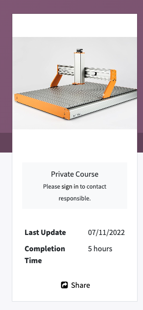
Click on the words “SIGN IN” – Note, that they are a link but do not show as underlined or highlighted but when you put your mouse over them, you will see the pointer change to click the link.
You will come to a page asking you to log in to your account. If you do not have an account on the website, please click the “Don’t have an account?” link
When you click on “Don’t have an account?” you will get a form to fill out to sign up for an account. Put in your email, full name and create and confirm a password.
Once you create an account, you will be brought back to the course page and this time you will see a new message in the left-hand box.
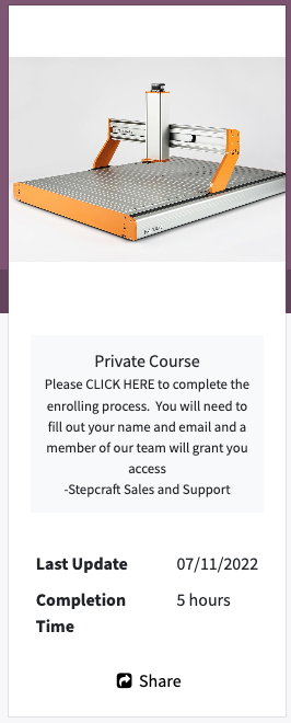
Click the link for “CLICK HERE” to complete the enrollment process. Again “CLICK HERE” is not graphically indicated as a link, but when you put your mouse over it, you will see your pointer change.
A popup window will appear asking if you want access to the course. Click YES
At this point, a member of our sales and support teams will be notified that you wish access to the course. This usually happens within 24 hours. Our team needs to ensure that you are a customer and link your account in our back-end system to this course for you. These courses were created specifically for STEPCRAFT-only customers which is why we use this verification process.
If you do not get access to the course within 24 hours, please email support@stepcraft.us
UCCNC
Why won’t the UCCNC installer complete when running the Stepcraft Multi-installer?
The most common cause that prevents the UCCNC installation from completing is due to the lack of Microsoft’s .NET Framework being installed. To do so, simply navigate to your Control Panel and select Programs. From there select the “Turn Windows Features on and off” option. Check the box for Microsoft .NET 3.5. Once your .NET framework is installed, continue with a fresh installation of UCCNC using the Stepcraft Multi-installer provided with your Stepcraft CNC system.
The most common cause for UCCNC running sluggish or slow, to the point where it is almost unusable, is because Windows had recently automatically installed an update in the background. This is most common when using Windows 10. CNC Drive, the makers of UCCNC software are very good with addressing these issues, however sometimes they have to wait until they even know there is an issue, which is usually when users notice the problem and contact CNCDrive or post online. If this happens to you before a UCCCNC update is available, then the fix is to uninstall the most recent Windows update (or updates). The following video shows you how to do this.
If this video still does not correct the problem, please email our support department at support@stepcraft.us
Why is the Yellow dot not in the location I set on my work piece in UCCNC?
In the live display window in UCCNC it shows you your project file as well as the location of the tool in real time. The tool is represented by a Yellow Dot on the screen. If you setup a job with the XY datum in the center of your job, then Yellow dot should be in the center of the screen in that window before you start running the job.
If the dot is NOT in the where you set it in your CAD/CAM file, then it is most likely because you did not ZERO X AND Y once you positioned the end mill (Spindle) at the starting location. Please use the following steps when you setup a job to ensure that your yellow dot is always where you want it before you run a job:
To ensure that your job is always setup properly, please follow these steps:
- Load your work piece onto the CNC and secure it
- Home your CNC machine (Press Home All on UCCNC)
- Manually move the end mill (spindle) to the location that you want to start the job on your work piece
- PRESS THE HOME BUTTON FOR Y AND X – this will reset the digital read out (DRO) to 0.00 for each.
- Load your GCode file – when you do you should notice that the yellow dot is where you set it up in your CAM file (lower left, center, etc)
- Set your Z Zero manually by lowering it to touch the material surface or machine bed (to match how your setup your CAM file) OR use a Tool Length Sensor
- Run your job!
Why is My UCR201 Jog Pendant Not Showing Up In UCCNC?
The UCR201 Jog Pendant requires the user to enable the plugin in the configuration window in UCCNC. If you are running version 1.2037 of UCCNC, you may find that the Jog Pendant does not show up in the configuration window. If this is the case, you simply need to update UCCNC to a newer version which can be found below…
UCCNC Version 1.2049 – http://www.cncdrive.com/UCCNC/download_UCCNC.php
After downloading and installing version 1.2049 of UCCNC, the Jog Pendant should now be visible in the configuration window and you can proceed with the rest of the setup!
How come my circles are not perfectly round?
When you are machining circles on a CNC and your circles are not coming out perfectly round, it is commonly caused because there is some backlash developing on the machine. Backlash is a tiny amount of play that appears over time and is noticed when a drive changes direction.
When running in a positive direction, the gears/lead screw are engaged with the lead screw nut on the gantry, but when the stepper motor reverses direction there is a tiny space between the lead screw and the lead screw nut that has to be made up before there is positive engagement in that direction. After many, many hours of use or if your machine is not properly maintained and lubricated, then this backlash can develop.
If this is happening to you, please download this document: Stepcraft UCCNC Backlash Compensation.
This will show you how to setup backlash compensation in UCCNC so that you can “dial” out any backlash and go back to having perfect circles again.
Where can I download UCCNC?
UCCNC is the machine control software that moves your STEPCRAFT machine and interprets G-Code. In order to use your STEPCRAFT machine, you will need the UCCNC software as well as the STEPCRAFT machine specific profiles. You can download and install both from the STEPCRAFT Multi-Installer that comes on your orange USB flash drive, or download here. STEPCRAFT will always have the latest compatible version of UCCNC included in the Multi-Installer. If you are looking for the newest released version of UCCNC, you can download here (note: UCCNC may release versions newer than those included on the STEPCRAFT Multi-Installer. These versions may not have been fully tested and may cause some bugs/issues with your machine. It is reccomended to use the version of UCCNC included on the STEPCRAFT Multi-Installer).
Where Can I Download the Stepcraft Multi-Installer?
The multi-Installer can be found on the orange USB flash drive sent with every D. series CNC system, or can be downloaded from the Dropbox link below.
Stepcraft D. Series Multi-Installer:
https://www.dropbox.com/s/vytptg88ahqbc8g/Stepcraft_Multi_Installer.exe?dl=0
What software comes with the machine?
STEPCRAFT, Inc (USA) includes UCCNC machine control software with each CNC system. The only software you need to additionally purchase is a CAD/CAM package like Vectric Cut 3D or V Carve.
STEPCRAFT in other parts of the world gives you the option to purchase the machines with UCCNC, WinPC-NC or without any machine control software.
After the initial launch of the M-Series line of CNC machines, a change was made in our driver system causing us to need two versions of the profile for the M.1000 machine.
How do I know which one I need? If you purchased your machine BEFORE April 2022, then you need the M.1000 profile. If you purchased AFTER April 2022, then you need the M.1000T profile.
How do I get the profile? Please contact our support department at support@stepcraft.us and we can assist you to ensure you have the correct profile.
What is the difference between the two profiles? The main difference is in the assignment of steps-per-inch (or steps-per-mm) for the newer driver cards. This profile ensures that UCCNC is configured properly for your driver card.
Are there any issues with the pre-2022 machines or drivers? NO. There are no performance, reliability, or accuracy issues with the original drivers. It is merely a software configuration change that we had to make.
Sometimes when you start UCCNC you will get the “Select the motion controller device from the list” message box that pops up. This is either happening because your UC100 interface or USB cable is unplugged or the device driver did not properly install. This video will show you how to fix this.
If you are still have trouble after watching this video, please contact our support team at support@stepcraft.us.
What does “The current job workspace is out of the set software limits” error window mean?
This error happens when your design is larger than the allowable work area on the CNC machine. Every machine has its own specific software profile that you install with UCCNC. This software profile tells UCCNC what the available work area size is on your machine. The main reason for this is to protect your machine from crashing into itself if you run a job that is larger than the machine’s capabilities. Think of the “software limits” as invisible limit switches. When you load a job into UCCNC, it looks at the G-Code automatically and compares the XYZ dimensions of your file against the software profile to make sure that the job can fit on your machine. If the settings in your file are larger than the work area, then you will get this error window.
Sometimes, if your job is NOT larger than the work area size for your machine and you get this error, you can reposition your work piece so when you zero X and Y that you fall within the work area. For example. Say your machine has a work area limits that are set to 420 mm on Y and 300 mm on X and you are trying to run a job that is 380 mm long x 280 mm wide. This job should work with no problem, however if you have the work piece positioned more than 20mm from the left side of the machines work area limit or 40 mm away from the front of the machine, and you have zeroed UCCNC in that position, then you will get this error when you start the job because it adds the job size to the position where you have X and Y zeroed and if that number is greater than 420 on Y or 300 on X it triggers the error.
It is important to take into account your “safe Z height” when encountering this error. If your safe Z height causes the Z-Axis to travel past the limits of the machine you will get this error. This is very common when working with thicker materials or long end mills. You can adjust your safe Z height in two places…
1.) In your CAD/CAM program. If you are using Vectric it will be under “Material Setup”.
2.) In UCCNC –> CONFIGURATION –> GENERAL SETTINGS. About half way down on the right side you have your “Safe Z height (Units). You can lower this number for more room.
The two values do stack, so if you are still having trouble try lowering both.
Another common cause for the error is to verify where your XY Datum is located in your design file. Many times a job might have been set with a XY datum of the lower left corner but the operator sets the machine up as if the XY Datum is in the center. This will, in most cases, cause the error because that zero position added to the jobs work size will exceed the software limits of the profile in UCCNC.
On rare occasions when you click the UCCNC installer, it will seem like it is going to run but then nothing happens. In order for UCCNC to properly install, it requires the .Net 2.0 framework and some Windows 10 machines, it is turned off by default. You can turn this on easily by following this video.
If after watching this video, you are still having problems, please email our support team at support@stepcraft.us
All STEPCRAFT software, including UCCNC and Vectric products require a Windows-based computer system or a Mac running Parallels with Windows.
- COMPUTER:
- 2 GHZ multi-core CPU
- 2 GB RAM with Windows XP (SP3), Windows Vista, Windows Version 7, 8, 8.1, or 10
- 300 Mb Disk Space (Vectric)
- 100 Mb Disk Space (UCCNC)
- DISPLAY
- 1024 x 768 graphics display
- OPERATING SYSTEM
- Windows XP (SP3), Windows Vista, Windows Version 7, 8, 8.1, or 10 with 2 GB RAM
If you wish to run Fusion 360, that can be run on both Windows machines and Mac computers natively.
Understanding the Homing Procedure
Whenever you open UCCNC, the very first movement you should make with your machine is “Home All”. On a STEPCRAFT, the homing procedure begins with the Z-Axis, then the X-Axis and finally the Y-Axis. Each axis will run towards its limit switch until it engages the switch, then will run the opposite way until the switch disengages. Once all three axis have hit their limit switch, your machine is now ready to travel the full length of each axis!
This is known as a reference movement for the machine. Without this reference movement, the machine has no idea where it is along its axis and may not travel the full length back and forth. If your machine is stopping short of the full length of travel and you aren’t noticing any binding, make sure to “Home All” and try running again.
One important thing to note is that if any axis ever travels in the opposite direction of its limit switch when homing, check to make sure a limit switch is not engaged somewhere on the machine. All of the limit switches are on the same circuit, so if you tried to home your machine and the Y-Axis limit switch was pressed, the Z-Axis would travel in the OPPOSITE direction. This happens because the machine is going through the stage of homing when it backs away from the switch until it disengages. Because the Y-Axis switch was pressed, the Z-Axis will infinitely try to move away but it will never disengage.
Please send an email to support@stepcraft.us and they will help you get a replacement.
My machine is in reset mode and I can not get it to reset, how can I fix this?
If your machine will not come out of reset mode, there are three things to check:
- Make sure that UCCNC is not running in Demo Mode. If UCCNC is running in demo mode, the software will not reset.
- Ensure that the emergency stop button is not press in on the front of the machine. You can disengage it by simply twisting it to the right slightly and it should pop out. If it is already out, then you can move on to #2.
- Check the Y Axis limit switch wires on the back of the machine. Sometimes these wires can be accidentally knocked out and become disconnected. Be sure both wires are plugged in correctly.
- Click on the DIAGNOSTICS tab in UCCNC. Check to see if any of the limit switch lights are on in the I/O Function Monitor. (Please see the video below starting at 1:36)
If I use Solidworks CAM or Fusion 360 CAM, do I still need to use UCCNC or Mach 3?
The purpose of any CAM program is to take your design file and turn it into G-Code by assigning tool paths to your project and outputting it in a format that a CNC machine can understand.
That being said, you still need a method of controlling the CNC machine, which is where programs like Mach 3 and UCCNC come in. They are designed to connect to the CNC machine and the G-Code files that you create in your CAM program are loaded into Mach 3 or UCCNC to run the machine.
With any CNC router, you have three main steps to creating a project:
- Design your project in a CAD/Drawing program
- Use a CAM program to assign tools and tool paths to the project
- Use a machine control program to load the G-Code files and run the CNC machine.
How many computers can I install UCCNC on?
There really is no limit, you just need to make sure you have the license file for the UC100 parallel to USB interface installed on each computer in the C://uccnc folder. The limitation is not how many computers you can install it on, it’s the fact that you can really only “use” it on the computer that has the UC100 connected to it. So if you have 5 computers with UCCNC installed, you would have to move the UC100 from computer to computer and connect to the CNC in order to use that computer. The software is linked to the UC100 hardware.
There are three basic software program types that you will need to have some knowledge of when getting ready to use your STEPCRAFT CNC system:
- A design or CAD program. Design programs like Adobe Illustrator, Inkscape, Corel Draw. CAD programs like AutoCAD, Fusion 360, Sketchup, Solidworks, etc. STEPCRAFT supports these and many more of the popular CAD/vector design software programs on the market. Depending on what you are looking to do will determine how much knowledge you will need to have on a CAD or design program
- A CAM (computer aided manufacturing) program. A CAM program will take the vectors or 3D model that you have designed and allow you to tell the program which tools you intent to use as well as the material size and the speeds and feed rate that you wish to run for your project. The CAM program will output a G Code file, which is basically common machine language for CNC machines. Vectric programs like V Carve and Cut 2D make this process pretty easy. STEPCRAFT sells and supports the full line of Vectric programs as well as Deskproto Multi-Axis CAM software.
- UCCNC (or machine control software). This program is used to setup, job and zero the STEPCRAFT CNC as well as loading and running the G Code file that was created from your CAM program.
So answer the question as to how easy it is to learn, really depends on what you are looking to do.
For example, if you are looking to do projects that are pretty complex and require that you design them in Fusion 360 or Illustrator, and you DON’T know how to use these programs, then you will have a longer learning curve since you will have to learn the design program as well.
Assuming that you already know how to use a design or CAD program, then the next program you would need to learn is a CAM program, such as Vectric V Carve. The nice thing about V Carve (or Cut 2D) is that the interface is very easy to learn so you can be on the way of making your first CNC project in a matter of minutes. However, as you progress, these programs have a lot of powerful features that will extend the limits on what you can create on your STEPCRAFT CNC machine.
As for UCCNC, this program takes about 15 minutes to learn how to use. Much of what you see on the screen are buttons and features that you will not use (unless doing advanced features like automatic tool changing, etc). There are only about 5 buttons that you will need to focus on to successfully start creating projects on your STEPCRAFT right away.
This video gives you a basic overview of the software programs and how easy it is to get started right away.
How do I Recover My UCCNC License File?
If you have misplaced or lost your UCCNC license key file, the process of recovering it is fast and easy. The serial number located on one side of your UC100 corresponds to your hard-coded license key, as shown below. Simply contact our support team and provide them with this serial number, and you will receive your recovered license file as an email attachment.
How can I reset my Stepcraft UCCNC installation?
Can’t seem to solve a strange bug or error? Can’t find a fix here? Mismatched or changed profile settings are a very common cause, but what if you cannot locate the setting that is giving you these issues?
A fresh installation will take care of making sure your profile settings match the default ones and make sure that you are not going in circles when troubleshooting UCCNC. This short video will walk you through each step required to not only remove any trace elements of your old installation, but also covers how to re-install your profiles to reduce downtime and get your machine back up and running.
Does the UCCNC installer contain a virus?!?
Some virus protection software companies have flagged the UCCNC installer as possibly containing a “trojan virus”. Rest assured, there is absolutly ZERO threat of a virus contained within the UCCNC installer. We are working diligently with the creators of UCCNC and companies such as Norton to have this flag removed so our customers can have a smooth installation process. For now, you may need to turn your virus protection off to install the UCCNC.exe file. You can immediately turn the software back on as soon as the program has been installed. We apologize for the inconvenience! If you have any questions or concerns, please feel free to give us a call directly at (203)556-1856.
STEPCRAFT CNC systems require that they are connected to a computer via a USB cable. Having the machine connected to a computer may not be as convenient but the ability to make file changes and reset parameters of the CNC from the computer saves a lot of time.]
Can I use a Mac with a STEPCRAFT CNC?
Yes! While the UCCNC and Vectric Software both run on Windows platforms, you can use a MAC as long as you run Parallels software which allows you to install Windows on your Mac. You can not run UCCNC or Vectric natively on a Mac (without Parallels). If you use Fusion 360 for CAD/CAM, then you can install that natively as they have a Mac version of that software. However, UCCNC will still need Parallels with Windows.
NOTE: Since a Mac computer is typically much more expensive than a Windows system, and the fact that UCCNC does not need a powerful computer, we recommend using your Mac for the design work and then getting an inexpensive or refurbished computer (desktop or laptop) to use to run the CNC, since the area around the CNC can potentially have dust and chips that might get on or near the computer.
Vectric Software (Cut 2D, Cut 3D, V Carve)
Why is the Yellow dot not in the location I set on my work piece in UCCNC?
In the live display window in UCCNC it shows you your project file as well as the location of the tool in real time. The tool is represented by a Yellow Dot on the screen. If you setup a job with the XY datum in the center of your job, then Yellow dot should be in the center of the screen in that window before you start running the job.
If the dot is NOT in the where you set it in your CAD/CAM file, then it is most likely because you did not ZERO X AND Y once you positioned the end mill (Spindle) at the starting location. Please use the following steps when you setup a job to ensure that your yellow dot is always where you want it before you run a job:
To ensure that your job is always setup properly, please follow these steps:
- Load your work piece onto the CNC and secure it
- Home your CNC machine (Press Home All on UCCNC)
- Manually move the end mill (spindle) to the location that you want to start the job on your work piece
- PRESS THE HOME BUTTON FOR Y AND X – this will reset the digital read out (DRO) to 0.00 for each.
- Load your GCode file – when you do you should notice that the yellow dot is where you set it up in your CAM file (lower left, center, etc)
- Set your Z Zero manually by lowering it to touch the material surface or machine bed (to match how your setup your CAM file) OR use a Tool Length Sensor
- Run your job!
Why is my project coming out incredibly small?
If your project is coming out incredibly small in UCCNC (e.g. 1/10th the size designed) you are most likely using the incorrect post processor. Every post processor used with a STEPCRAFT machine should end in (mm). This is because UCCNC will only accept millimeters as a parameter! Even if your project is designed entirely in inches, the (mm) post processors will automatically do the conversion from inch to mm for UCCNC to properly interpret. This means that you can design in inches, millimeters or anything you choose, and the post processor will always do the proper conversions for you. It is a very common mistake to select the (inch) post processor when working in inches. This will NOT do the proper conversion and UCCNC will interpret every inch measurement as a millimeter measurement. This is why the project, when saved with the incorrect (inch) post processor, will come out very small.
We have a special post processor that you need to use for the laser. You can download that file [here]
You need to place the file in the correct folder in your Vectric Program.
Do do this, open your program (V Carve, Cut 2D, etc)
In the FILE Menu, select OPEN APPLICATION DATA FOLDER
Look for a “PostP” or “My_PostP” folder
Copy the laser post processor file (downloaded above) Into both of these folders.
NOTE: if you copy the file into the My_PostP folder then when you open your Vectric Program, only the post processors in this folder will show. So I always recommend copying the post processors for my CNC into this folder so when you go to create a G Code file, you will not have to scan though a ton of files for other machines. If you do not want to use the My_PostP folder then simply copy the above Laser profile into the PostP folder and you will see it in the list of post processors.
ALSO, you will need to restart the program for the post processor to be visible in the list
What software comes with the machine?
STEPCRAFT, Inc (USA) includes UCCNC machine control software with each CNC system. The only software you need to additionally purchase is a CAD/CAM package like Vectric Cut 3D or V Carve.
STEPCRAFT in other parts of the world gives you the option to purchase the machines with UCCNC, WinPC-NC or without any machine control software.
What post processor do I use for Vectric programs (Aspire, VCarve, Cut 2d, Cut 3D, PhotoVCarve)?
NOTE: These post processors will work for BOTH UCCNC and WIN-PC NC
From the dropdown list in Vectric programs, you will look for the following
If you have an Automatic Tool Changer: Stepcraft UCCNC ATC Arcs (mm) (*.txt)
If you do not have an Automatic Tool Changer: Stepcraft UCCNC Arcs (mm) (*.txt)
If you have an older version of Vectric software and the STEPCRAFT post processors are NOT in the dropdown list, please use the following:
If you have an Automatic Tool Changer: Mach2/3 ATC Arcs (mm) (*.txt)
If you do not have an Automatic Tool Changer: Mach2/3 Arcs (mm) (*.txt)
A CNC Router is (typically) a 3 axis machine.
Y Axis – front to back motion
X Axis – Side to side (left/right) motion
Z Axis – Up and down motion.
2.5D milling refers to the CNC’s ability to move the cutter along X and Y in a synchronized manner with the Z axis moving only a predetermined about during each pass. As an example, if you were cutting a square that was 2″ x 2″ all the way through 1/2″ material and you want a hole in the center of the square that is .75″ in diameter but you only want it to go down .25″, the machine will move X and Y to form the circle and Z will lower after each pass depending on the depth per pass setting in your software. So if you have depth per pass set to .125″, then the first pass will make the circle with the Z lowered .125″ so the circle will be .125″ deep after the first pass, then it will lower another .125″ for the second and final pass. When it is done you will have a circle that is “pocketed” .25″ deep into the material.
When the perimeter of the square is cut out, X and Y will move around the square, again with Z lowering .125″ per pass until it reaches the .5″ material thickness.
When 2.5D milling, all depths that you cut will be flat bottomed with 90 degree sides. So the bit will only plunge straight into the workpiece.
Most CAM programs support 2.5D milling. Vectric Cut 2D and V Carve do a great job.
3D milling refers to the CNC’s ability to move X, Y and Z all at the same time in a synchronized fashion to create contoured bottoms, sides and tops of objects. Many times this will be called 3D carving of material. Depending on the shape that you are carving, you will most likely be using a ball nose end mill to provide smooth contoured surfaces.
Vectric Cut 3D and V Carve support 3D milling/carving operations
What is G-Code?
G-Code is the generic name for CNC machine control language. It is the way that you can tell a computerized machine (CNC machine) to make something. G-Code consists of instructions that tell the CNC machine where to move, how fast to move and what path to follow. As the machine is following the G-Code, it is continually removing material (except in the case of a 3D printer, where it is adding material) leaving behind a finished part.
You do not need to know how to program G-Code to run many of today’s personal desktop CNC machines. STEPCRAFT recommends using CAD/CAM software like Fusion 360, Vectric VCarve, Cut 2D or Cut 3D or Deskproto. These programs have an intuitive graphical interface that allows you to set all of the parameters for your job and then the software will output a fully-formatted G-Code file that you can load into your CNC’s machine control program to run the job.
It is, however, not a bad idea to learn the basics of G-Code so if there was ever a problem with a job, you can quickly reference the code and see and understand what the machine is doing (or supposed to do) for the given G-Code commands.
All STEPCRAFT software, including UCCNC and Vectric products require a Windows-based computer system or a Mac running Parallels with Windows.
- COMPUTER:
- 2 GHZ multi-core CPU
- 2 GB RAM with Windows XP (SP3), Windows Vista, Windows Version 7, 8, 8.1, or 10
- 300 Mb Disk Space (Vectric)
- 100 Mb Disk Space (UCCNC)
- DISPLAY
- 1024 x 768 graphics display
- OPERATING SYSTEM
- Windows XP (SP3), Windows Vista, Windows Version 7, 8, 8.1, or 10 with 2 GB RAM
If you wish to run Fusion 360, that can be run on both Windows machines and Mac computers natively.
The importing of images for use and processing with the STEPCRAFT CNC is purely dependent on the CAM software that you are using. For example, Vectric Cut 2D and V Carve both allow the importing of images in the following formats: .bmp, .jpg, .gif, .tif, .tiff, .png and .jpeg. You can not import native files from Pagemaker, Word, etc., only common bitmap formats.
If you have an image in another format or from another program, you can always import them into a graphics program like GIMP or Photoshop and then output them from there.
I want to buy a STEPCRAFT Complete System package, but I want VCarve Pro rather than Desktop, how can I do this?
All of the complete system packages, with the exception of the ELITE comes with Vectric VCarve Desktop software which will have a 24×24″ size limitation. If you are looking to order the 840 CNC, then you will NOT be able to use the entire work bed with a single file using VCarve Desktop. So you would need to VCarve Pro. You can click this link https://stepcraft.us/product/package-upgrade-to-v-carve-pro/ to add the “UPGRADE” to your order. Please NOTE that this is ONLY the upgrade and can only be used in conjunction with a complete system that has VCarve Desktop.
There are three basic software program types that you will need to have some knowledge of when getting ready to use your STEPCRAFT CNC system:
- A design or CAD program. Design programs like Adobe Illustrator, Inkscape, Corel Draw. CAD programs like AutoCAD, Fusion 360, Sketchup, Solidworks, etc. STEPCRAFT supports these and many more of the popular CAD/vector design software programs on the market. Depending on what you are looking to do will determine how much knowledge you will need to have on a CAD or design program
- A CAM (computer aided manufacturing) program. A CAM program will take the vectors or 3D model that you have designed and allow you to tell the program which tools you intent to use as well as the material size and the speeds and feed rate that you wish to run for your project. The CAM program will output a G Code file, which is basically common machine language for CNC machines. Vectric programs like V Carve and Cut 2D make this process pretty easy. STEPCRAFT sells and supports the full line of Vectric programs as well as Deskproto Multi-Axis CAM software.
- UCCNC (or machine control software). This program is used to setup, job and zero the STEPCRAFT CNC as well as loading and running the G Code file that was created from your CAM program.
So answer the question as to how easy it is to learn, really depends on what you are looking to do.
For example, if you are looking to do projects that are pretty complex and require that you design them in Fusion 360 or Illustrator, and you DON’T know how to use these programs, then you will have a longer learning curve since you will have to learn the design program as well.
Assuming that you already know how to use a design or CAD program, then the next program you would need to learn is a CAM program, such as Vectric V Carve. The nice thing about V Carve (or Cut 2D) is that the interface is very easy to learn so you can be on the way of making your first CNC project in a matter of minutes. However, as you progress, these programs have a lot of powerful features that will extend the limits on what you can create on your STEPCRAFT CNC machine.
As for UCCNC, this program takes about 15 minutes to learn how to use. Much of what you see on the screen are buttons and features that you will not use (unless doing advanced features like automatic tool changing, etc). There are only about 5 buttons that you will need to focus on to successfully start creating projects on your STEPCRAFT right away.
This video gives you a basic overview of the software programs and how easy it is to get started right away.
You can go to Vectric’s website http://www.vectric.com/store/upgrades.html. There you will be given the pricing for upgrading your version of VCarve.

Do I have to design my files in metric because I see that UCCNC is metric?
No, You can design in inches or metric. If you are using Vectric programs, you can design in inches or metric because when you choose the post processor to create your file, the post processor will convert the G Code to metric.
For more information on which post processor to use, please see this FAQ: https://cncfaq.us/ufaqs/post-processor-use-vectric-programs-vcarve-cut-2d-cut-3d-photovcarve/
If you wish to learn the Vectric software while you are waiting for your STEPCRAFT CNC to arrive, your best bet is to download a FREE full working trial copy of the software from Vectric’s website.
The trial versions will not allow you to save a toolpath for your CNC other than the special sample files that are included. However any files that are created and saved with the trial versions of Cut2D, VCarve Pro, Aspire or Cut3D can be opened and made fully operational once you purchase and install the full version of the software as long as it is installed on the same PC as the trial version software.
Important: Please note that the Trial version of the software cannot be ‘Activated’ with the license key you receive when you purchase a copy. The trial versions of the software are for testing and evaluation only. It is not possible to license them to become full versions. You will however be supplied with a CD with your order which you can install and overwrite the trial copy.
Can you scan your own design and create a tool path to cut the object out on a CNC (Image Tracing)?
Vectric software, such as Cut 2D and VCarve have the ability for you to import a bitmap image and then use a function called “Image Trace” to create a vector around the image. You can then adjust and modify the vector to your liking. From there you can select the vector(s) and create a tool path for the CNC machine to cut around. You can also vary the depth of the cut to meet your specific needs.
The following video show you how to do this:
Can I use a Mac with a STEPCRAFT CNC?
Yes! While the UCCNC and Vectric Software both run on Windows platforms, you can use a MAC as long as you run Parallels software which allows you to install Windows on your Mac. You can not run UCCNC or Vectric natively on a Mac (without Parallels). If you use Fusion 360 for CAD/CAM, then you can install that natively as they have a Mac version of that software. However, UCCNC will still need Parallels with Windows.
NOTE: Since a Mac computer is typically much more expensive than a Windows system, and the fact that UCCNC does not need a powerful computer, we recommend using your Mac for the design work and then getting an inexpensive or refurbished computer (desktop or laptop) to use to run the CNC, since the area around the CNC can potentially have dust and chips that might get on or near the computer.
Can I use a 3D scanner to create 3D models to carve as well as 3D print?
Yes, models created with a 3D Scanner are typically saved in common 3D formats like a .stl. These files can be imported into CAM programs like Vectric Cut 3D, Vectric V Carve and Deskproto where they can be assigned tool paths to carve the object out of a material. This is commonly done with two tool paths: Roughing and Finishing, using a standard end mill and a ball nose end mill, respectively.
These files created from a 3D scanner can also be used for a 3D printer.
Here is a good article with a list of the best 3D scanners for 2017: https://pinshape.com/blog/the-11-best-3d-scanners-on-the-market/
STEPCRAFT also has a 3D Touch Probe which can be used for 3D scanning. The following videos show how that works:
Yes you can download a full working trial copy for free. Please see this FAQ
Can I engrave a photograph into a piece of wood?
Yes, you can use Vectric’s PhotoVCarve program, which allows you to create an engraving tool path for photos.
Additionally, you can use the new Laser Engraving Head DL445 which can laser engrave your photos into a variety of materials.
Working With Carbon Fiber
How come my circles are not perfectly round?
When you are machining circles on a CNC and your circles are not coming out perfectly round, it is commonly caused because there is some backlash developing on the machine. Backlash is a tiny amount of play that appears over time and is noticed when a drive changes direction.
When running in a positive direction, the gears/lead screw are engaged with the lead screw nut on the gantry, but when the stepper motor reverses direction there is a tiny space between the lead screw and the lead screw nut that has to be made up before there is positive engagement in that direction. After many, many hours of use or if your machine is not properly maintained and lubricated, then this backlash can develop.
If this is happening to you, please download this document: Stepcraft UCCNC Backlash Compensation.
This will show you how to setup backlash compensation in UCCNC so that you can “dial” out any backlash and go back to having perfect circles again.
What is the total usable Z height on the D-Series CNC?
The D-Series 420, 600 and 840 all have a max Z height of 140mm (5.51″). However this does not represent the maximum height of material you can process. From this height you need to subtract the spindle collet nut stick out as well as the length of the cutting tool you are using.
The following represents the spindle and spindle nut stick out you get on a D-Series machine with the HF-500 and MM-1000 spindles
HF-500: 31mm (1.22″)
MM-1000: 38.6mm (1.52″)
MM-1000 (with single spacer): 32.56mm (1.28″)
MM-1000 (with dual spacers): 26.34mm (1.04″)
- NOTE: This is the case with just about every CNC machine on the market, not just STEPCRAFT CNC. Most all CNC machines will have spindle and spindle nut/tool holder stick out that takes away from the usable Z height.
So if you take into consideration the MM-1000 with dual spacers, you would have a total Z height of 140mm (5.51″) minus 26.34mm (1.04″) leaving you with a new max Z height of 113.66mm (4.47″).
Now depending on what you intend to do, you can use this new value to plan your project. If you want to cut all the way through material, you would need to have a tool that is long enough, which you would further subtract from the new Z height value.
Example 1: New Z Value is 113.66mm (4.47″), if you divide that number in half, that would mean you can use a piece of material that is 56.83mm (2.23″) thick and the tool would have to stick out 56.83mm (2.23″) as well.
- NOTE: This would also mean that the cutting height of the tool would have to be a min of 56.83mm (2.23″) or you run the risk of rubbing the shank of the tool on the material.
Example 2: If you intend to only engrave on top of a piece of material, then your tool stick out can be much less. If you use an engraving blank that sticks out say 12mm from the bottom of the collet nut, then that means you can have a max material height of 101.66mm (4″).
- NOTE: please keep in mind you should also allow for a couple 2-3mm of Z height clearance for rapid, non-cutting moves on the CNC as well. So you would subtract another 2-3mm from the above numbers in a practical application.
TWO SIDED MACHINING – For thicker material
One way that you can increase your max material thickness that you can cut through is using double sided machining.
Example: You can take your new Z value of 113.66mm (4.47″) and divide that into thirds. This would mean you can have a material thickness of 75.33mm (2.96″), or two-thirds and using a cutter with a length of 38mm (1.49″) you can cut one side of the project and then flip it over and cut the other side – so you are using a shorter cutter to cut through a thicker material by cutting each side.
Example:
What is a surfacing bit used for?
A surfacing bit typically has a larger than normal cutting diameter (1 to 3 inches) and are used to flatten or level uneven surfaces on your project material. They are also used to take the thickness of a material down to a final required size. For example, you might have a piece of rough cut lumber that measures 1 inch in thickness but you need it to be 3/4 inch thick. If you don’t have a surface planer in your shop then you can use a surfacing bit with a pocket tool path to plane the material down.
Another common use for surfacing bits is to clean up and level a spoil board. After continuous use your spoil board’s surface will have a lot of cuts in it and you might want to clean it up so it is perfectly smooth again. A surfacing bit is perfect for this, especially with machines where the spoil board is physically attached to the machine – you might want to prolong the use of it for as long as you can before replacing.
Leveling your spoil board is also important. If you are looking to engrave .005″ into a piece of metal and your bed is off by a couple thousandths from one side to the other or front to back, then the thickness of your engraved lines will vary. By using a surfacing bit, you will ensure that your spoil board is perfectly level in relation to your gantry which will result in a uniform engraving.
Note: Because of the larger diameter of a surfacing bit, it is important to note that you can not take as deep of passes or run as fast as you might with smaller end mills on most machines. Consult your machine’s manufacturer for assistance with proper speeds and feeds for surfacing bits.
Is the STEPCRAFT CNC system able to engrave or cut through carbon fibers?
Yes, the STEPCRAFT CNC will cut carbon fiber very well and very accurately. However, due to the hazardous nature of the carbon dust, STEPCRAFT has a Milling Bath that can be used where you cut the Carbon in water and the water captures the dust not allowing it to become airborne. You can see the Milling Bath here: https://stepcraft.us/product/milling-bath-840/ (They are available in sizes for the 420, 600 and 840 machines)
The following videos show you how well a STEPCRAFT can do with Carbon Fiber:
Can I cut carbon fiber on the STEPCRAFT CNC?
Yes, you can. In fact, carbon fiber cuts very easily on the STEPCRAFT. The main issue with cutting carbon is the dust that is created is very hazardous to your health if you breathe it in. To combat this, STEPCRAFT has a Milling Bath in three separate sizes for the 420, 600 and 840 machines. You can find information on the Milling Baths here: https://stepcraft.us/product-category/accessories/system-accessories-accessories/cnc-accessories/
Additionally here are a couple videos that you can watch containing more information on using a STEPCRAFT CNC for carbon fiber.
Working With Metals
Will the milling and laser tools work on other metals besides aluminum?
Yes, they will also machine brass and copper. STEPCRAFT machines are only designed for machining of non-ferrous metals. So you can not mill steel, stainless steel, etc.
Also note that the laser will NOT cut metals. you can use it to engrave but it will NOT cut!
How come my circles are not perfectly round?
When you are machining circles on a CNC and your circles are not coming out perfectly round, it is commonly caused because there is some backlash developing on the machine. Backlash is a tiny amount of play that appears over time and is noticed when a drive changes direction.
When running in a positive direction, the gears/lead screw are engaged with the lead screw nut on the gantry, but when the stepper motor reverses direction there is a tiny space between the lead screw and the lead screw nut that has to be made up before there is positive engagement in that direction. After many, many hours of use or if your machine is not properly maintained and lubricated, then this backlash can develop.
If this is happening to you, please download this document: Stepcraft UCCNC Backlash Compensation.
This will show you how to setup backlash compensation in UCCNC so that you can “dial” out any backlash and go back to having perfect circles again.
What is the total usable Z height on the D-Series CNC?
The D-Series 420, 600 and 840 all have a max Z height of 140mm (5.51″). However this does not represent the maximum height of material you can process. From this height you need to subtract the spindle collet nut stick out as well as the length of the cutting tool you are using.
The following represents the spindle and spindle nut stick out you get on a D-Series machine with the HF-500 and MM-1000 spindles
HF-500: 31mm (1.22″)
MM-1000: 38.6mm (1.52″)
MM-1000 (with single spacer): 32.56mm (1.28″)
MM-1000 (with dual spacers): 26.34mm (1.04″)
- NOTE: This is the case with just about every CNC machine on the market, not just STEPCRAFT CNC. Most all CNC machines will have spindle and spindle nut/tool holder stick out that takes away from the usable Z height.
So if you take into consideration the MM-1000 with dual spacers, you would have a total Z height of 140mm (5.51″) minus 26.34mm (1.04″) leaving you with a new max Z height of 113.66mm (4.47″).
Now depending on what you intend to do, you can use this new value to plan your project. If you want to cut all the way through material, you would need to have a tool that is long enough, which you would further subtract from the new Z height value.
Example 1: New Z Value is 113.66mm (4.47″), if you divide that number in half, that would mean you can use a piece of material that is 56.83mm (2.23″) thick and the tool would have to stick out 56.83mm (2.23″) as well.
- NOTE: This would also mean that the cutting height of the tool would have to be a min of 56.83mm (2.23″) or you run the risk of rubbing the shank of the tool on the material.
Example 2: If you intend to only engrave on top of a piece of material, then your tool stick out can be much less. If you use an engraving blank that sticks out say 12mm from the bottom of the collet nut, then that means you can have a max material height of 101.66mm (4″).
- NOTE: please keep in mind you should also allow for a couple 2-3mm of Z height clearance for rapid, non-cutting moves on the CNC as well. So you would subtract another 2-3mm from the above numbers in a practical application.
TWO SIDED MACHINING – For thicker material
One way that you can increase your max material thickness that you can cut through is using double sided machining.
Example: You can take your new Z value of 113.66mm (4.47″) and divide that into thirds. This would mean you can have a material thickness of 75.33mm (2.96″), or two-thirds and using a cutter with a length of 38mm (1.49″) you can cut one side of the project and then flip it over and cut the other side – so you are using a shorter cutter to cut through a thicker material by cutting each side.
Example:
This really depends on the bit you are using and what the flute length is. If you are using a bit with a 0.5″ flute length then your maximum thickness would be 0.5″. Keep in mind that when you go thicker than 0.125″ thick aluminum, you have to be very careful to take care of chip evacuation. When your end mill starts to make a deep channel that is the width of the bit, then chips will fall in the channel and when the bit rotates, it can recut the chips causing excessive heat, chatter, welding of the chips to the tip of the bit or breaking the bit. A way around this for deeper cuts is to create a pocket around the perimeter that is wider than the bit so if chips fall in the channel they are not “forced” into the wall by the cutter. You should also use compressed air to continually blow the chips away from the bit and the channel.
We have successfully cut through 1″ thick aluminum blocks without a problem. Keep in mind that this is a CNC router and not a CNC mill, so it is not designed to be as aggressive with your feeds, speeds and pass depths. Take care to not push the machine, spindle or end mill past its limits.
What is a surfacing bit used for?
A surfacing bit typically has a larger than normal cutting diameter (1 to 3 inches) and are used to flatten or level uneven surfaces on your project material. They are also used to take the thickness of a material down to a final required size. For example, you might have a piece of rough cut lumber that measures 1 inch in thickness but you need it to be 3/4 inch thick. If you don’t have a surface planer in your shop then you can use a surfacing bit with a pocket tool path to plane the material down.
Another common use for surfacing bits is to clean up and level a spoil board. After continuous use your spoil board’s surface will have a lot of cuts in it and you might want to clean it up so it is perfectly smooth again. A surfacing bit is perfect for this, especially with machines where the spoil board is physically attached to the machine – you might want to prolong the use of it for as long as you can before replacing.
Leveling your spoil board is also important. If you are looking to engrave .005″ into a piece of metal and your bed is off by a couple thousandths from one side to the other or front to back, then the thickness of your engraved lines will vary. By using a surfacing bit, you will ensure that your spoil board is perfectly level in relation to your gantry which will result in a uniform engraving.
Note: Because of the larger diameter of a surfacing bit, it is important to note that you can not take as deep of passes or run as fast as you might with smaller end mills on most machines. Consult your machine’s manufacturer for assistance with proper speeds and feeds for surfacing bits.
No, you do not need to use different spindles. The main factor will be how fast the feed rate will be that you run and how much material you remove per pass.
If you with to run a light duty spindle like a Dremel 4000, you can run wood, plastics and metals just as well as if you were using a Kress 800W spindle. The only difference is that you will not be able to remove as much material and your feed rate will be slower the harder the material is.
Keep in mind that dedicated CNC spindles will have better quality bearings which will offer less runout and therefore a longer life span and higher accuracy. Using the Dremel example, this device is not meant for hours and hours of prolonged use, nor is it made to have lots of pressure side loading the main shaft. You will find that if you are not careful on the feed rate and pass depth that you will quickly wear out the bearings.
A router like the Dewalt DW611 will also cut all types of material, but as with the Dremel, the bearings are not as good as with a dedicated spindle so you can expect more runout with a router. The STEPCRAFT HF500 is a purpose built spindle that was designed to work with all types of materials and has an excellent bearing system that provides very little runout and a much higher accuracy.
The bottom line is that you can pretty much cut whatever you like with just about any spindle. You just need to be cautious on feed rates and pass depth.
No, the STEPCRAFT is only designed to cut non-ferrous metals like brass, aluminum and copper. You might be able to engrave steel with the right engraving bit and proper speed and feed settings, but you can not cut it.
Can I use MDF as a spoil board when cutting aluminum?
Often times when cutting aluminum you will need a spoil board under the aluminum, especially when you are cutting all the way through the material. MDF is a very common material to use as a spoil board for the following reasons:
- There is no grain so it cuts the same in any direction
- It is usually pretty flat
- It cuts easily so when your bit goes through your work piece, there is no additional strain on it when it makes contact with the MDF
- It is easy to find and relatively inexpensive.
Some things to be careful of when machining aluminum with an MDF spoil board:
- Make sure the MDF is secured well to the machine bed
- Make sure the Aluminum is clamped tight to the MDF/machine bed – if it is not you will get vibration, chatter, poor cut finish, and can possibly break your cutting bit.
- You can not use any lubricant when you use an MDF spoil board! It will swell and expand if it gets wet. So using spray or mist coolant or oils like Tap Magic is not recommended.
An alternative spoil board that we use is acrylic. Acrylic is hard, flat, easier to machine than aluminum so it will not strain your machine and if you want/need to use lubricant, then you can without worrying about it damaging the spoil board.
No. While there are some “general purpose” end mills that will cut aluminum, some end mills are designed specifically for plastic, foam, wood or other non-metal materials.
Working With Plastics
How come my circles are not perfectly round?
When you are machining circles on a CNC and your circles are not coming out perfectly round, it is commonly caused because there is some backlash developing on the machine. Backlash is a tiny amount of play that appears over time and is noticed when a drive changes direction.
When running in a positive direction, the gears/lead screw are engaged with the lead screw nut on the gantry, but when the stepper motor reverses direction there is a tiny space between the lead screw and the lead screw nut that has to be made up before there is positive engagement in that direction. After many, many hours of use or if your machine is not properly maintained and lubricated, then this backlash can develop.
If this is happening to you, please download this document: Stepcraft UCCNC Backlash Compensation.
This will show you how to setup backlash compensation in UCCNC so that you can “dial” out any backlash and go back to having perfect circles again.
What is the total usable Z height on the D-Series CNC?
The D-Series 420, 600 and 840 all have a max Z height of 140mm (5.51″). However this does not represent the maximum height of material you can process. From this height you need to subtract the spindle collet nut stick out as well as the length of the cutting tool you are using.
The following represents the spindle and spindle nut stick out you get on a D-Series machine with the HF-500 and MM-1000 spindles
HF-500: 31mm (1.22″)
MM-1000: 38.6mm (1.52″)
MM-1000 (with single spacer): 32.56mm (1.28″)
MM-1000 (with dual spacers): 26.34mm (1.04″)
- NOTE: This is the case with just about every CNC machine on the market, not just STEPCRAFT CNC. Most all CNC machines will have spindle and spindle nut/tool holder stick out that takes away from the usable Z height.
So if you take into consideration the MM-1000 with dual spacers, you would have a total Z height of 140mm (5.51″) minus 26.34mm (1.04″) leaving you with a new max Z height of 113.66mm (4.47″).
Now depending on what you intend to do, you can use this new value to plan your project. If you want to cut all the way through material, you would need to have a tool that is long enough, which you would further subtract from the new Z height value.
Example 1: New Z Value is 113.66mm (4.47″), if you divide that number in half, that would mean you can use a piece of material that is 56.83mm (2.23″) thick and the tool would have to stick out 56.83mm (2.23″) as well.
- NOTE: This would also mean that the cutting height of the tool would have to be a min of 56.83mm (2.23″) or you run the risk of rubbing the shank of the tool on the material.
Example 2: If you intend to only engrave on top of a piece of material, then your tool stick out can be much less. If you use an engraving blank that sticks out say 12mm from the bottom of the collet nut, then that means you can have a max material height of 101.66mm (4″).
- NOTE: please keep in mind you should also allow for a couple 2-3mm of Z height clearance for rapid, non-cutting moves on the CNC as well. So you would subtract another 2-3mm from the above numbers in a practical application.
TWO SIDED MACHINING – For thicker material
One way that you can increase your max material thickness that you can cut through is using double sided machining.
Example: You can take your new Z value of 113.66mm (4.47″) and divide that into thirds. This would mean you can have a material thickness of 75.33mm (2.96″), or two-thirds and using a cutter with a length of 38mm (1.49″) you can cut one side of the project and then flip it over and cut the other side – so you are using a shorter cutter to cut through a thicker material by cutting each side.
Example:
What is the correct end mill and speeds and feeds for Dibond or MaxMetal?
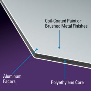
MaxMetal/Dibond is a very common material used in the sign world. It is basically two thin pre-painted sheets of 0.012″ aluminum with a solid polyethylene black core. Some, as in our sample video, come as brushed aluminum or in a brass color which have the look and durability of aluminum without the price. The material is very easy to cut on a CNC.
The best settings to cut MaxMetal/Dibond on a STEPCRAFT D-Series CNC System are:
End Mill/Cutting Tool: Amana 51411 1/4″ shank, 1/8″ Cutting Diameter
Feed Rate: 33 mm/sec
Pass Depth: 0.0625″
RPM: 16,000
Ramp: 1″ smooth
NOTE: Be careful NOT to have double-sided tape under the cutting path or it can gum up the end mill and cause melting on the plastic core and/or affect the finish quality of the final cut on the metal.
The Video below shows an example of cutting this material with the above settings on a STEPCRAFT D.840 with an MM-1000 Spindle.
What is the best bit or end mill to use when cutting Acrylic, and what are the best speeds and feeds?
Acrylic is a very common material to cut on a CNC. It can be used for anything from making windows in projects to making edge-lit LED signs. Acrylic can be a tricky material to cut successfully, mainly because many people will run the RPM of the cutter too fast with a feed rate that is too slow, thus causing melting of the plastic. The trick is to get nice clean chips as you cut.
The following article goes into this in detail: Cutting Acrylic – 8 Guidelines To Getting The Best Results
What is a surfacing bit used for?
A surfacing bit typically has a larger than normal cutting diameter (1 to 3 inches) and are used to flatten or level uneven surfaces on your project material. They are also used to take the thickness of a material down to a final required size. For example, you might have a piece of rough cut lumber that measures 1 inch in thickness but you need it to be 3/4 inch thick. If you don’t have a surface planer in your shop then you can use a surfacing bit with a pocket tool path to plane the material down.
Another common use for surfacing bits is to clean up and level a spoil board. After continuous use your spoil board’s surface will have a lot of cuts in it and you might want to clean it up so it is perfectly smooth again. A surfacing bit is perfect for this, especially with machines where the spoil board is physically attached to the machine – you might want to prolong the use of it for as long as you can before replacing.
Leveling your spoil board is also important. If you are looking to engrave .005″ into a piece of metal and your bed is off by a couple thousandths from one side to the other or front to back, then the thickness of your engraved lines will vary. By using a surfacing bit, you will ensure that your spoil board is perfectly level in relation to your gantry which will result in a uniform engraving.
Note: Because of the larger diameter of a surfacing bit, it is important to note that you can not take as deep of passes or run as fast as you might with smaller end mills on most machines. Consult your machine’s manufacturer for assistance with proper speeds and feeds for surfacing bits.
Can I use MDF as a spoil board when cutting aluminum?
Often times when cutting aluminum you will need a spoil board under the aluminum, especially when you are cutting all the way through the material. MDF is a very common material to use as a spoil board for the following reasons:
- There is no grain so it cuts the same in any direction
- It is usually pretty flat
- It cuts easily so when your bit goes through your work piece, there is no additional strain on it when it makes contact with the MDF
- It is easy to find and relatively inexpensive.
Some things to be careful of when machining aluminum with an MDF spoil board:
- Make sure the MDF is secured well to the machine bed
- Make sure the Aluminum is clamped tight to the MDF/machine bed – if it is not you will get vibration, chatter, poor cut finish, and can possibly break your cutting bit.
- You can not use any lubricant when you use an MDF spoil board! It will swell and expand if it gets wet. So using spray or mist coolant or oils like Tap Magic is not recommended.
An alternative spoil board that we use is acrylic. Acrylic is hard, flat, easier to machine than aluminum so it will not strain your machine and if you want/need to use lubricant, then you can without worrying about it damaging the spoil board.
Working With Woods
How come my circles are not perfectly round?
When you are machining circles on a CNC and your circles are not coming out perfectly round, it is commonly caused because there is some backlash developing on the machine. Backlash is a tiny amount of play that appears over time and is noticed when a drive changes direction.
When running in a positive direction, the gears/lead screw are engaged with the lead screw nut on the gantry, but when the stepper motor reverses direction there is a tiny space between the lead screw and the lead screw nut that has to be made up before there is positive engagement in that direction. After many, many hours of use or if your machine is not properly maintained and lubricated, then this backlash can develop.
If this is happening to you, please download this document: Stepcraft UCCNC Backlash Compensation.
This will show you how to setup backlash compensation in UCCNC so that you can “dial” out any backlash and go back to having perfect circles again.
What is the total usable Z height on the D-Series CNC?
The D-Series 420, 600 and 840 all have a max Z height of 140mm (5.51″). However this does not represent the maximum height of material you can process. From this height you need to subtract the spindle collet nut stick out as well as the length of the cutting tool you are using.
The following represents the spindle and spindle nut stick out you get on a D-Series machine with the HF-500 and MM-1000 spindles
HF-500: 31mm (1.22″)
MM-1000: 38.6mm (1.52″)
MM-1000 (with single spacer): 32.56mm (1.28″)
MM-1000 (with dual spacers): 26.34mm (1.04″)
- NOTE: This is the case with just about every CNC machine on the market, not just STEPCRAFT CNC. Most all CNC machines will have spindle and spindle nut/tool holder stick out that takes away from the usable Z height.
So if you take into consideration the MM-1000 with dual spacers, you would have a total Z height of 140mm (5.51″) minus 26.34mm (1.04″) leaving you with a new max Z height of 113.66mm (4.47″).
Now depending on what you intend to do, you can use this new value to plan your project. If you want to cut all the way through material, you would need to have a tool that is long enough, which you would further subtract from the new Z height value.
Example 1: New Z Value is 113.66mm (4.47″), if you divide that number in half, that would mean you can use a piece of material that is 56.83mm (2.23″) thick and the tool would have to stick out 56.83mm (2.23″) as well.
- NOTE: This would also mean that the cutting height of the tool would have to be a min of 56.83mm (2.23″) or you run the risk of rubbing the shank of the tool on the material.
Example 2: If you intend to only engrave on top of a piece of material, then your tool stick out can be much less. If you use an engraving blank that sticks out say 12mm from the bottom of the collet nut, then that means you can have a max material height of 101.66mm (4″).
- NOTE: please keep in mind you should also allow for a couple 2-3mm of Z height clearance for rapid, non-cutting moves on the CNC as well. So you would subtract another 2-3mm from the above numbers in a practical application.
TWO SIDED MACHINING – For thicker material
One way that you can increase your max material thickness that you can cut through is using double sided machining.
Example: You can take your new Z value of 113.66mm (4.47″) and divide that into thirds. This would mean you can have a material thickness of 75.33mm (2.96″), or two-thirds and using a cutter with a length of 38mm (1.49″) you can cut one side of the project and then flip it over and cut the other side – so you are using a shorter cutter to cut through a thicker material by cutting each side.
Example:
STEPCRAFT CNC machines have two parameters in the specifications for their machines: Clamping Surface and Travel Distance
Clamping Surface is maximum size of work material that you can place onto the machines bed. Travel Distance is the maximum amount that the gantry and cutting bit will move.
As an example, the STEPCRAFT-2/300 has a clamping surface of 14.96″ x 8.74″ (380x222mm) but the travel distance is equal to 11.81″ x 8.27″ (300x210mm). This means that you can place a slightly larger workpiece onto the bed than you can actually cut.
The number that is most important when choosing which size STEPCRAFT machine to buy is the Travel Distance.
The following chart reflects these sizes as well as the overall dimension of the machines. Clamping Distance is the middle set of dimensions and Travel Distance is the Lower Set of Dimensions.
What is the maximum height of the work material that I can place on the work bed?
The total travel distance for the Z axis is 5.5″. However, you need to keep in mind that some of that height will be used up by the systemheld tool that you place on the machine. For example, the HF500 spindle and collet stick below the tool holder by about 1.2″ This would reduce the total material height to 4.3″ From that you need to account for the length of the tool as well.
What is a surfacing bit used for?
A surfacing bit typically has a larger than normal cutting diameter (1 to 3 inches) and are used to flatten or level uneven surfaces on your project material. They are also used to take the thickness of a material down to a final required size. For example, you might have a piece of rough cut lumber that measures 1 inch in thickness but you need it to be 3/4 inch thick. If you don’t have a surface planer in your shop then you can use a surfacing bit with a pocket tool path to plane the material down.
Another common use for surfacing bits is to clean up and level a spoil board. After continuous use your spoil board’s surface will have a lot of cuts in it and you might want to clean it up so it is perfectly smooth again. A surfacing bit is perfect for this, especially with machines where the spoil board is physically attached to the machine – you might want to prolong the use of it for as long as you can before replacing.
Leveling your spoil board is also important. If you are looking to engrave .005″ into a piece of metal and your bed is off by a couple thousandths from one side to the other or front to back, then the thickness of your engraved lines will vary. By using a surfacing bit, you will ensure that your spoil board is perfectly level in relation to your gantry which will result in a uniform engraving.
Note: Because of the larger diameter of a surfacing bit, it is important to note that you can not take as deep of passes or run as fast as you might with smaller end mills on most machines. Consult your machine’s manufacturer for assistance with proper speeds and feeds for surfacing bits.
Is the chuck reversible on the 4th Axis unit?
Yes you can remove the three tabs from the chuck and put them in the opposite way to allow for a larger opening for larger stock, up to 2 inches in diameter.
To remove them, simply turn the inner ring behind the chuck counterclockwise and the threads will push the chuck tabs out. Then you can flip them around and while putting pressure on them turn the inner ring clockwise and they will be threaded back in.
Many CNC machines will offer a dust boot or adapter that surrounds the spindle with a brush or rubber gasket material that rubs along the workpiece. A vacuum is connected to this adapter and dust is extracted right at the end mill. STEPCRAFT, for example, offers an exhaust adapter with a removable brush.
To get the most out of your dust collection system you need to make sure that the brush is contacting the work surface. If not then only a percentage of the dust will be drawn into the dust collection system. Depending on the system you might need to use shorter bits to achieve this.
To extract the dust you can use a simple shop vac or an integrated dust collection system.
No, you do not need to use different spindles. The main factor will be how fast the feed rate will be that you run and how much material you remove per pass.
If you with to run a light duty spindle like a Dremel 4000, you can run wood, plastics and metals just as well as if you were using a Kress 800W spindle. The only difference is that you will not be able to remove as much material and your feed rate will be slower the harder the material is.
Keep in mind that dedicated CNC spindles will have better quality bearings which will offer less runout and therefore a longer life span and higher accuracy. Using the Dremel example, this device is not meant for hours and hours of prolonged use, nor is it made to have lots of pressure side loading the main shaft. You will find that if you are not careful on the feed rate and pass depth that you will quickly wear out the bearings.
A router like the Dewalt DW611 will also cut all types of material, but as with the Dremel, the bearings are not as good as with a dedicated spindle so you can expect more runout with a router. The STEPCRAFT HF500 is a purpose built spindle that was designed to work with all types of materials and has an excellent bearing system that provides very little runout and a much higher accuracy.
The bottom line is that you can pretty much cut whatever you like with just about any spindle. You just need to be cautious on feed rates and pass depth.
Can I use MDF as a spoil board when cutting aluminum?
Often times when cutting aluminum you will need a spoil board under the aluminum, especially when you are cutting all the way through the material. MDF is a very common material to use as a spoil board for the following reasons:
- There is no grain so it cuts the same in any direction
- It is usually pretty flat
- It cuts easily so when your bit goes through your work piece, there is no additional strain on it when it makes contact with the MDF
- It is easy to find and relatively inexpensive.
Some things to be careful of when machining aluminum with an MDF spoil board:
- Make sure the MDF is secured well to the machine bed
- Make sure the Aluminum is clamped tight to the MDF/machine bed – if it is not you will get vibration, chatter, poor cut finish, and can possibly break your cutting bit.
- You can not use any lubricant when you use an MDF spoil board! It will swell and expand if it gets wet. So using spray or mist coolant or oils like Tap Magic is not recommended.
An alternative spoil board that we use is acrylic. Acrylic is hard, flat, easier to machine than aluminum so it will not strain your machine and if you want/need to use lubricant, then you can without worrying about it damaging the spoil board.
Can I engrave a photograph into a piece of wood?
Yes, you can use Vectric’s PhotoVCarve program, which allows you to create an engraving tool path for photos.
Additionally, you can use the new Laser Engraving Head DL445 which can laser engrave your photos into a variety of materials.