
Frequently Asked Questions (FAQ)
FAQ CATEGORIES
3D Print Questions
Why my 3D printer head (PH40) goes into Stand-By mode while working
The printers are going into standby and eventually shutting off because they are not receiving the correct signal from UCCNC that the machine is running. This is a very simple fix outlined below.
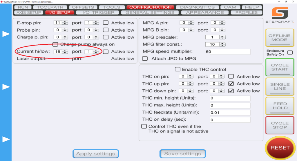
1.) Define pin outs in UCCNC –> CONFIGURATION –> I/O SETUP. On the left hand side you have “Current hi/low”. Those two pins should read “16” and “1”.
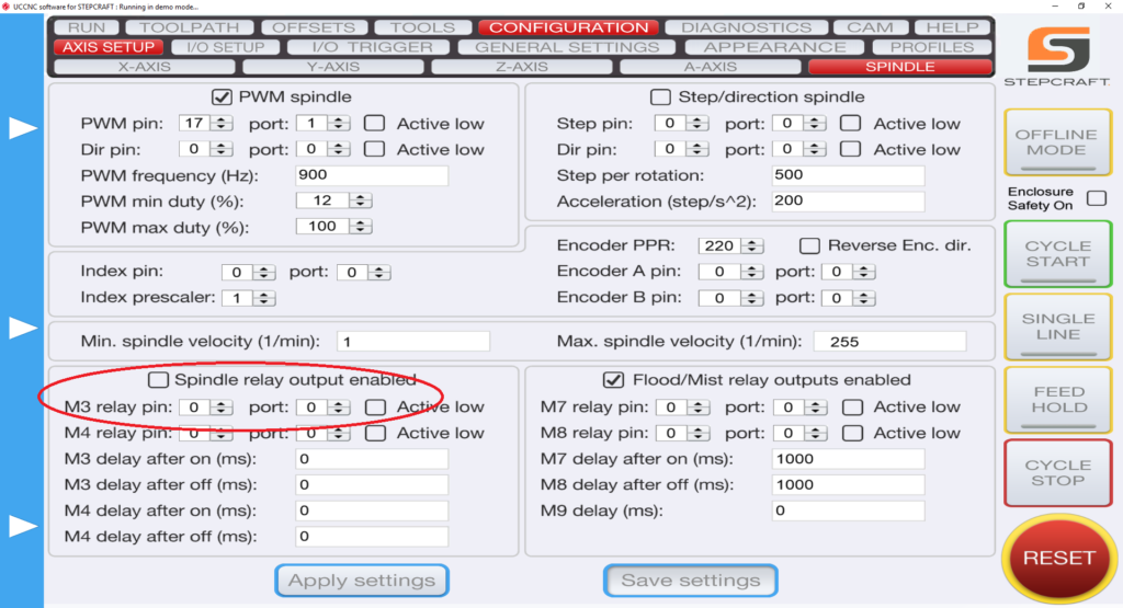
2.) Define pin outs in UCCNC –> AXIS SETUP –> SPINDLE. Bottom Left you have “M3 relay pin”. Change those values to “0” and “0” and uncheck the “spindle relay output enabled” if it is checked.
Does the Laser DL445 use the same port on the STEPCRAFT as the 3D Printer and HF500 spindle?
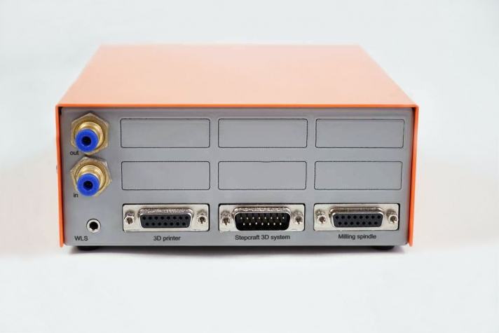
Yes, they both use the same serial port on the back of the machine. You would need to disconnect the cable and reconnect the attachment that you wish to use. STEPCRAFT also offers a Switchbox which allows you to connect everything and simply turn the dial to select the attachment you wish to use. This is very handy if you are constantly changing attachments.

Can I connect my HF-500/MM-1000 spindle and 3D printer to the STEPCRAFT at the same time?
Yes you can with the use of the of the STEPCRAFT System Attachment Switch Box. To use the Switch Box, you simply plug a serial cable from the Switch Box to the serial port on the CNC and then you plug the 3D Printer and the HF500 Spindle into the respective ports on the back of the box. Then you can just rotate the dial to select the attachment that you would like to use and mount that attachment into the tool holder on the STEPCRAFT.
Automatic Tool Changer
How Can I Calibrate My Tool Length Sensor?
If you find that your tool length sensor (TLS) is functioning properly, but not touching the very top of your material, you may need to preform a quick calibration. This ensures that the tool length sensor is accurate and reliable. The following video will walk you through the simple TLS calibration…
Before You Buy A CNC Router
Why is My UCR201 Jog Pendant Not Showing Up In UCCNC?
The UCR201 Jog Pendant requires the user to enable the plugin in the configuration window in UCCNC. If you are running version 1.2037 of UCCNC, you may find that the Jog Pendant does not show up in the configuration window. If this is the case, you simply need to update UCCNC to a newer version which can be found below…
UCCNC Version 1.2049 – http://www.cncdrive.com/UCCNC/download_UCCNC.php
After downloading and installing version 1.2049 of UCCNC, the Jog Pendant should now be visible in the configuration window and you can proceed with the rest of the setup!
You can think of the Semi-Closed Loop System as an “electronic insurance policy”. The system uses a special sensor that is installed on each of the 4 CNC motors. This sensor monitors the movement of each motor and compares that movement against what UCCNC is telling it to move.
As an example, if UCCNC wants to move X 35mm to the right and something is interfering with that movement and it only moves 31mm, then the Semi Closed Loop System will immediately stop the system.
The beauty of this system is that you can simply rehome the machine and then continue the job right where you left off. This is especially handy when you are using expensive materials that you do not want to waste.
It is comprised of 4 sensors, one mounted on each of the Y-axis motors, one on X and one on Z. The sensors monitor the motors’ movements and compare that movement against what UCCNC (your project’s G-Code file) is telling the motor to move. In the event that one of the motors does not match the intended movement, then the system will immediately go into E-Stop.
As your machine is cutting a project, if it runs into an obstruction, or if there is any other situation that causes the machine to stall in one of the axes, it will stop the system.
To reset, you can simply rehome the machine and then continue running the job from where you left off. You can use the RUN FROM HERE button on UCCNC and the job will continue as if the error never happened. You can watch the following video to learn how to use this feature on UCCNC:
How do I connect my Remote Switchable Power Controller?
To connect your remote switchable power controller system, follow the diagram below…

Common Pre-Purchase Questions
Why my 3D printer head (PH40) goes into Stand-By mode while working
The printers are going into standby and eventually shutting off because they are not receiving the correct signal from UCCNC that the machine is running. This is a very simple fix outlined below.
1.) Define pin outs in UCCNC –> CONFIGURATION –> I/O SETUP. On the left hand side you have “Current hi/low”. Those two pins should read “16” and “1”.
2.) Define pin outs in UCCNC –> AXIS SETUP –> SPINDLE. Bottom Left you have “M3 relay pin”. Change those values to “0” and “0” and uncheck the “spindle relay output enabled” if it is checked.
You can think of the Semi-Closed Loop System as an “electronic insurance policy”. The system uses a special sensor that is installed on each of the 4 CNC motors. This sensor monitors the movement of each motor and compares that movement against what UCCNC is telling it to move.
As an example, if UCCNC wants to move X 35mm to the right and something is interfering with that movement and it only moves 31mm, then the Semi Closed Loop System will immediately stop the system.
The beauty of this system is that you can simply rehome the machine and then continue the job right where you left off. This is especially handy when you are using expensive materials that you do not want to waste.
It is comprised of 4 sensors, one mounted on each of the Y-axis motors, one on X and one on Z. The sensors monitor the motors’ movements and compare that movement against what UCCNC (your project’s G-Code file) is telling the motor to move. In the event that one of the motors does not match the intended movement, then the system will immediately go into E-Stop.
As your machine is cutting a project, if it runs into an obstruction, or if there is any other situation that causes the machine to stall in one of the axes, it will stop the system.
To reset, you can simply rehome the machine and then continue running the job from where you left off. You can use the RUN FROM HERE button on UCCNC and the job will continue as if the error never happened. You can watch the following video to learn how to use this feature on UCCNC:
If an error has occurred or your system has an obstruction causing the Semi-Closed Loop System to trigger, it will activate the E-Stop mode on the machine. When this happens the first thing you need to do is take note of the line number that you are at in the G-Code window on the lower left part of the UCCNC screen. Write it down or take a photo with your cell phone.
To reset this, you press the Red reset button on the UCCNC screen and then press HOME ALL. This will reset each axis so that everything is back in sync with UCCNC. From that point, you can use the START FROM HERE button and restart the job from right where you left off.
You can view this video on how to use the START FROM HERE button:
Can I cut carbon fiber on the STEPCRAFT CNC?
Yes, you can. In fact, carbon fiber cuts very easily on the STEPCRAFT. The main issue with cutting carbon is the dust that is created is very hazardous to your health if you breathe it in. To combat this, STEPCRAFT has a Milling Bath in three separate sizes for the 420, 600 and 840 machines. You can find information on the Milling Baths here: https://stepcraft.us/product-category/accessories/system-accessories-accessories/cnc-accessories/
Additionally here are a couple videos that you can watch containing more information on using a STEPCRAFT CNC for carbon fiber.
Can I buy the STEPCRAFT Touch Probe for use with a non-STEPCRAFT CNC machine?
Yes, you can purchase the Touch Probe and it will most likely work with just about any CNC. However, you be responsible for the correct software setup, macros and configuration for your system. STEPCRAFT will NOT support the operation or configuration of the Touch Probe for non-STEPCRAFT machines. The unit will, however, be warranted for mechanical defects.
Education
Why is My UCR201 Jog Pendant Not Showing Up In UCCNC?
The UCR201 Jog Pendant requires the user to enable the plugin in the configuration window in UCCNC. If you are running version 1.2037 of UCCNC, you may find that the Jog Pendant does not show up in the configuration window. If this is the case, you simply need to update UCCNC to a newer version which can be found below…
UCCNC Version 1.2049 – http://www.cncdrive.com/UCCNC/download_UCCNC.php
After downloading and installing version 1.2049 of UCCNC, the Jog Pendant should now be visible in the configuration window and you can proceed with the rest of the setup!
How Can I Calibrate My Tool Length Sensor?
If you find that your tool length sensor (TLS) is functioning properly, but not touching the very top of your material, you may need to preform a quick calibration. This ensures that the tool length sensor is accurate and reliable. The following video will walk you through the simple TLS calibration…
Hardware Troubleshooting
If an error has occurred or your system has an obstruction causing the Semi-Closed Loop System to trigger, it will activate the E-Stop mode on the machine. When this happens the first thing you need to do is take note of the line number that you are at in the G-Code window on the lower left part of the UCCNC screen. Write it down or take a photo with your cell phone.
To reset this, you press the Red reset button on the UCCNC screen and then press HOME ALL. This will reset each axis so that everything is back in sync with UCCNC. From that point, you can use the START FROM HERE button and restart the job from right where you left off.
You can view this video on how to use the START FROM HERE button:
Laser Cutter/Engraver Questions
Why my laser positioning light is not visible?
- Turn the power key switch to the ON position.
- Move the laser head approx. 20mm above work piece to focus positioning laser beam clearly.
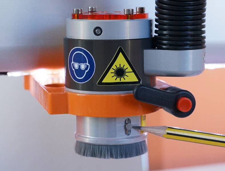
- To enable the positioning light, move the zero point sensor to the middle position and the light should turn on.
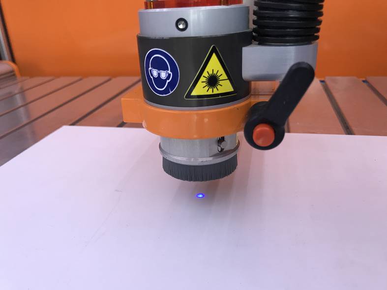
The positioning light is a class 2 laser with far less power (comparable to a laser pointer).
If your laser positioning guide wont turn on after following this procedure please contact our support team and they can guide you on how to fix this issue.
We have a special post processor that you need to use for the laser. You can download that file [here]
You need to place the file in the correct folder in your Vectric Program.
Do do this, open your program (V Carve, Cut 2D, etc)
In the FILE Menu, select OPEN APPLICATION DATA FOLDER

Look for a “PostP” or “My_PostP” folder

Copy the laser post processor file (downloaded above) Into both of these folders.
NOTE: if you copy the file into the My_PostP folder then when you open your Vectric Program, only the post processors in this folder will show. So I always recommend copying the post processors for my CNC into this folder so when you go to create a G Code file, you will not have to scan though a ton of files for other machines. If you do not want to use the My_PostP folder then simply copy the above Laser profile into the PostP folder and you will see it in the list of post processors.
ALSO, you will need to restart the program for the post processor to be visible in the list
Does the Laser DL445 use the same port on the STEPCRAFT as the 3D Printer and HF500 spindle?
Yes, they both use the same serial port on the back of the machine. You would need to disconnect the cable and reconnect the attachment that you wish to use. STEPCRAFT also offers a Switchbox which allows you to connect everything and simply turn the dial to select the attachment you wish to use. This is very handy if you are constantly changing attachments.
Maintenance
Why is My UCR201 Jog Pendant Not Showing Up In UCCNC?
The UCR201 Jog Pendant requires the user to enable the plugin in the configuration window in UCCNC. If you are running version 1.2037 of UCCNC, you may find that the Jog Pendant does not show up in the configuration window. If this is the case, you simply need to update UCCNC to a newer version which can be found below…
UCCNC Version 1.2049 – http://www.cncdrive.com/UCCNC/download_UCCNC.php
After downloading and installing version 1.2049 of UCCNC, the Jog Pendant should now be visible in the configuration window and you can proceed with the rest of the setup!
How do I connect my Remote Switchable Power Controller?
To connect your remote switchable power controller system, follow the diagram below…
How Can I Calibrate My Tool Length Sensor?
If you find that your tool length sensor (TLS) is functioning properly, but not touching the very top of your material, you may need to preform a quick calibration. This ensures that the tool length sensor is accurate and reliable. The following video will walk you through the simple TLS calibration…
RMC 100 Wireless Controller
Why is My UCR201 Jog Pendant Not Showing Up In UCCNC?
The UCR201 Jog Pendant requires the user to enable the plugin in the configuration window in UCCNC. If you are running version 1.2037 of UCCNC, you may find that the Jog Pendant does not show up in the configuration window. If this is the case, you simply need to update UCCNC to a newer version which can be found below…
UCCNC Version 1.2049 – http://www.cncdrive.com/UCCNC/download_UCCNC.php
After downloading and installing version 1.2049 of UCCNC, the Jog Pendant should now be visible in the configuration window and you can proceed with the rest of the setup!
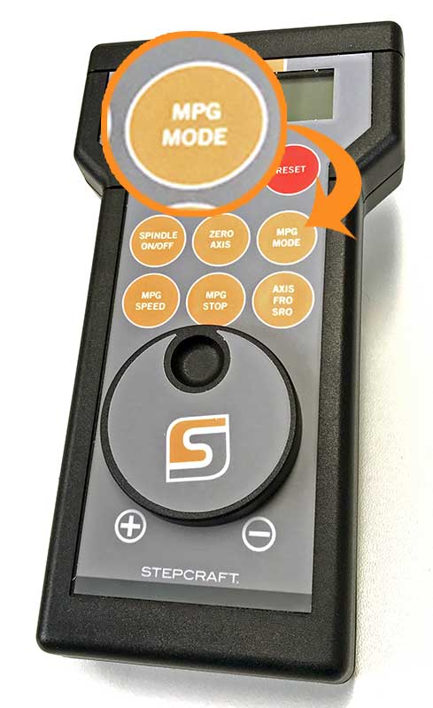
What is “MPG” on the STEPCRAFT RMC 100 Wireless Controller?
The term “MPG” stands for Manual Pulse Generator and is basically and electronic hand wheel. Selecting “MPG Mode” will allow you to rotate the wheel and move the axis on the machine in steps based on the indents in the wheel. This is a great way to move the spindle around, specifically when setting the starting position for each job.
Software Troubleshooting
Why my 3D printer head (PH40) goes into Stand-By mode while working
The printers are going into standby and eventually shutting off because they are not receiving the correct signal from UCCNC that the machine is running. This is a very simple fix outlined below.
1.) Define pin outs in UCCNC –> CONFIGURATION –> I/O SETUP. On the left hand side you have “Current hi/low”. Those two pins should read “16” and “1”.
2.) Define pin outs in UCCNC –> AXIS SETUP –> SPINDLE. Bottom Left you have “M3 relay pin”. Change those values to “0” and “0” and uncheck the “spindle relay output enabled” if it is checked.
If an error has occurred or your system has an obstruction causing the Semi-Closed Loop System to trigger, it will activate the E-Stop mode on the machine. When this happens the first thing you need to do is take note of the line number that you are at in the G-Code window on the lower left part of the UCCNC screen. Write it down or take a photo with your cell phone.
To reset this, you press the Red reset button on the UCCNC screen and then press HOME ALL. This will reset each axis so that everything is back in sync with UCCNC. From that point, you can use the START FROM HERE button and restart the job from right where you left off.
You can view this video on how to use the START FROM HERE button:
Spindles and Routers
My Q-Series will turn on while pressing the green button, but will not stay energized.
Your E-Stop could be active. Check to make sure the E-Stop in the front face of your machine is not engaged. Also, the US 110 volt edition of Q-Series machine has an additional spindle safety circuit to check – Make sure your 110 volt plug from the back of the machine is connected to a live power source, or, your spindle safety override switch (located on the top of the machine) is engaged.


How do I connect my Remote Switchable Power Controller?
To connect your remote switchable power controller system, follow the diagram below…
Does the Laser DL445 use the same port on the STEPCRAFT as the 3D Printer and HF500 spindle?
Yes, they both use the same serial port on the back of the machine. You would need to disconnect the cable and reconnect the attachment that you wish to use. STEPCRAFT also offers a Switchbox which allows you to connect everything and simply turn the dial to select the attachment you wish to use. This is very handy if you are constantly changing attachments.
Can I connect my HF-500/MM-1000 spindle and 3D printer to the STEPCRAFT at the same time?
Yes you can with the use of the of the STEPCRAFT System Attachment Switch Box. To use the Switch Box, you simply plug a serial cable from the Switch Box to the serial port on the CNC and then you plug the 3D Printer and the HF500 Spindle into the respective ports on the back of the box. Then you can just rotate the dial to select the attachment that you would like to use and mount that attachment into the tool holder on the STEPCRAFT.
STEPCRAFT Assembly Questions
Why is My UCR201 Jog Pendant Not Showing Up In UCCNC?
The UCR201 Jog Pendant requires the user to enable the plugin in the configuration window in UCCNC. If you are running version 1.2037 of UCCNC, you may find that the Jog Pendant does not show up in the configuration window. If this is the case, you simply need to update UCCNC to a newer version which can be found below…
UCCNC Version 1.2049 – http://www.cncdrive.com/UCCNC/download_UCCNC.php
After downloading and installing version 1.2049 of UCCNC, the Jog Pendant should now be visible in the configuration window and you can proceed with the rest of the setup!
How do I connect my Remote Switchable Power Controller?
To connect your remote switchable power controller system, follow the diagram below…
STEPCRAFT Attachments and Accessories
Will the D-Series Machines fit into the enclosure with the Performance Upgrade Kit added?
Yes, the machines will fit into their respective enclosures if you decide to add the performance kit to the the machine.
The Performance Upgrade is a new product that allows you to convert your D-Series D.840, D.600, or D.420 to dual Y axis motors thus eliminating the drive belt and increasing performance from 50 mm/sec to 70 mm/sec.


For more information on the performance kits, please visit: https://www.stepcraft.us/shop?search=performance
Why my 3D printer head (PH40) goes into Stand-By mode while working
The printers are going into standby and eventually shutting off because they are not receiving the correct signal from UCCNC that the machine is running. This is a very simple fix outlined below.
1.) Define pin outs in UCCNC –> CONFIGURATION –> I/O SETUP. On the left hand side you have “Current hi/low”. Those two pins should read “16” and “1”.
2.) Define pin outs in UCCNC –> AXIS SETUP –> SPINDLE. Bottom Left you have “M3 relay pin”. Change those values to “0” and “0” and uncheck the “spindle relay output enabled” if it is checked.
Why is My UCR201 Jog Pendant Not Showing Up In UCCNC?
The UCR201 Jog Pendant requires the user to enable the plugin in the configuration window in UCCNC. If you are running version 1.2037 of UCCNC, you may find that the Jog Pendant does not show up in the configuration window. If this is the case, you simply need to update UCCNC to a newer version which can be found below…
UCCNC Version 1.2049 – http://www.cncdrive.com/UCCNC/download_UCCNC.php
After downloading and installing version 1.2049 of UCCNC, the Jog Pendant should now be visible in the configuration window and you can proceed with the rest of the setup!
Why my laser positioning light is not visible?
- Turn the power key switch to the ON position.
- Move the laser head approx. 20mm above work piece to focus positioning laser beam clearly.
- To enable the positioning light, move the zero point sensor to the middle position and the light should turn on.
The positioning light is a class 2 laser with far less power (comparable to a laser pointer).
If your laser positioning guide wont turn on after following this procedure please contact our support team and they can guide you on how to fix this issue.
We have a special post processor that you need to use for the laser. You can download that file [here]
You need to place the file in the correct folder in your Vectric Program.
Do do this, open your program (V Carve, Cut 2D, etc)
In the FILE Menu, select OPEN APPLICATION DATA FOLDER
Look for a “PostP” or “My_PostP” folder
Copy the laser post processor file (downloaded above) Into both of these folders.
NOTE: if you copy the file into the My_PostP folder then when you open your Vectric Program, only the post processors in this folder will show. So I always recommend copying the post processors for my CNC into this folder so when you go to create a G Code file, you will not have to scan though a ton of files for other machines. If you do not want to use the My_PostP folder then simply copy the above Laser profile into the PostP folder and you will see it in the list of post processors.
ALSO, you will need to restart the program for the post processor to be visible in the list
What STEPCRAFT attachment will I need to cut thin sticker-type foil to make stickers or stencils?
The STEPCRAFT Drag Knife will work fine for this. Please see: https://stepcraft.us/product/drag-knife/
What software is recommended to run the Touch Probe?
STEPCRAFT customers can use UCCNC for the Touch Probe. We have a special screenset and macros to control it for various functions (DOWNLOAD HERE). For 3D object scanning with the Touch Probe, you will need a CAD/CAM program like Vectric Cut2D or VCarve to be able to draw a box and create a simple tool path for the scanning area. Once a point cloud file is created, you can download Meshlab (www.meshlab.net) for free, which will convert the point cloud file into a STL 3D file that you can CNC machine.
Non-STEPCRAFT customers will need to setup a macro for their machine control software to allow it to work. You would need to reference your software’s manufacturer to obtain information on this.
The videos below will give you much more information the setup and use of the STEPCRAFT TOUCH PROBE
What is the Mini Tool Adapter (P# 10120) used for?
The Mini Tool Adapter is used to reduce the size of our 43mm x 20mm adapter down to an 8mm hole so you can use STEPCRAFT attachments like the Engraving Point, Plotting Pen or 3D Touch Probe, which all have an 8mm shank on them.
Alternatively you can use an 8mm Collet in your spindle (Just be sure to power the spindle OFF) when running these attachments.


What is “MPG” on the STEPCRAFT RMC 100 Wireless Controller?
The term “MPG” stands for Manual Pulse Generator and is basically and electronic hand wheel. Selecting “MPG Mode” will allow you to rotate the wheel and move the axis on the machine in steps based on the indents in the wheel. This is a great way to move the spindle around, specifically when setting the starting position for each job.
You can think of the Semi-Closed Loop System as an “electronic insurance policy”. The system uses a special sensor that is installed on each of the 4 CNC motors. This sensor monitors the movement of each motor and compares that movement against what UCCNC is telling it to move.
As an example, if UCCNC wants to move X 35mm to the right and something is interfering with that movement and it only moves 31mm, then the Semi Closed Loop System will immediately stop the system.
The beauty of this system is that you can simply rehome the machine and then continue the job right where you left off. This is especially handy when you are using expensive materials that you do not want to waste.
What collet sizes come with the HF-500 spindle?
The HF-500 Spindle comes with 1/8″ and 1/4″ collets. It uses standard ER11 collets and you can get them in metric sizes as well. The 1/4″ is the largest that they make for ER11 and 8mm is the largest metric size.
My Q-Series will turn on while pressing the green button, but will not stay energized.
Your E-Stop could be active. Check to make sure the E-Stop in the front face of your machine is not engaged. Also, the US 110 volt edition of Q-Series machine has an additional spindle safety circuit to check – Make sure your 110 volt plug from the back of the machine is connected to a live power source, or, your spindle safety override switch (located on the top of the machine) is engaged.
I have a HF-500 Spindle and I want to add an Engraving Point, how can I do this?
To use the engraving point you have a couple options
1) you can get an 8mm collet and then simply put the engraving point into the collet like you would an end mill – just make sure the HF500 is powered off – link to collet: https://www.stepcraft.us/shop/product/10040-008-er11-collet-8mm-for-hf-500-spindle-and-mm-1000-automatic-tool-changer-291?search=8mm
2) If you want to remove the HF500 then you will need two tool adapters: Links: https://www.stepcraft.us/shop/product/10120-mini-tool-adapter-from-20-mm-to-8-mm-29?search=mini AND https://www.stepcraft.us/shop/product/10107-tool-adapter-from-43-mm-to-20mm-proxxon-28?search=proxxon
It is comprised of 4 sensors, one mounted on each of the Y-axis motors, one on X and one on Z. The sensors monitor the motors’ movements and compare that movement against what UCCNC (your project’s G-Code file) is telling the motor to move. In the event that one of the motors does not match the intended movement, then the system will immediately go into E-Stop.
As your machine is cutting a project, if it runs into an obstruction, or if there is any other situation that causes the machine to stall in one of the axes, it will stop the system.
To reset, you can simply rehome the machine and then continue running the job from where you left off. You can use the RUN FROM HERE button on UCCNC and the job will continue as if the error never happened. You can watch the following video to learn how to use this feature on UCCNC:
How do I setup and install the Tool Length Sensor on my STEPCRAFT CNC?
The Tool Length sensor is a great addition to your Stepcraft 2 machine, saving time in zeroing the Z axis. There are two ways to connect your Tool Length Sensor to your machine.
1. Using the Quick Connect 3.5mm Jack:
Your Tool Length Sensor comes with a 3.5mm male headphone jack. Most are already installed, but if you find your jack is not installed, refer to the soldering instructions included with the sensor. Simply plug the male jack into the female jack on the back of the main board. To check to make sure your sensor is functioning, under the UCCNC Diagnostics page, your “Probe” indicator should light up green when you press the Tool Length Sensor button and go away when disengaged. Its important to make sure the jumper in front of the wire TLS connector is present and connected on both of the pins.


2. Wiring Directly to the Main Board:
If you do not have a 3.5mm male or female jack (not included on older versions of the main board), you can wire your Tool Length Sensor directly to the main board. Strip the two wires at the end of the sensor (brown and white are the two most common) and install directly to the board terminals. The correct terminals are listed on the board itself and in your machine manual. Unplug or position it only on 1 pin the jumper to enable the internal Tool Length Sensor terminals.

Using the sensor:
After homing your machine setup your machine with some test material and place the sensor on top. Move the axis over the sensor and zero all. Now press the tool probe button from the main screen. The Z axis will lower slowly until it contacts the sensor. It will then retract and calculate the Z zero taking into account the height of the sensor. Move the sensor out of the way and you can now click Go to Zero. The Z axis will lower to the calculated height for the work material.

If an error has occurred or your system has an obstruction causing the Semi-Closed Loop System to trigger, it will activate the E-Stop mode on the machine. When this happens the first thing you need to do is take note of the line number that you are at in the G-Code window on the lower left part of the UCCNC screen. Write it down or take a photo with your cell phone.
To reset this, you press the Red reset button on the UCCNC screen and then press HOME ALL. This will reset each axis so that everything is back in sync with UCCNC. From that point, you can use the START FROM HERE button and restart the job from right where you left off.
You can view this video on how to use the START FROM HERE button:
How do I connect my Remote Switchable Power Controller?
To connect your remote switchable power controller system, follow the diagram below…
How Can I Calibrate My Tool Length Sensor?
If you find that your tool length sensor (TLS) is functioning properly, but not touching the very top of your material, you may need to preform a quick calibration. This ensures that the tool length sensor is accurate and reliable. The following video will walk you through the simple TLS calibration…
Does the Laser DL445 use the same port on the STEPCRAFT as the 3D Printer and HF500 spindle?
Yes, they both use the same serial port on the back of the machine. You would need to disconnect the cable and reconnect the attachment that you wish to use. STEPCRAFT also offers a Switchbox which allows you to connect everything and simply turn the dial to select the attachment you wish to use. This is very handy if you are constantly changing attachments.
Can I cut carbon fiber on the STEPCRAFT CNC?
Yes, you can. In fact, carbon fiber cuts very easily on the STEPCRAFT. The main issue with cutting carbon is the dust that is created is very hazardous to your health if you breathe it in. To combat this, STEPCRAFT has a Milling Bath in three separate sizes for the 420, 600 and 840 machines. You can find information on the Milling Baths here: https://stepcraft.us/product-category/accessories/system-accessories-accessories/cnc-accessories/
Additionally here are a couple videos that you can watch containing more information on using a STEPCRAFT CNC for carbon fiber.
Can I connect my HF-500/MM-1000 spindle and 3D printer to the STEPCRAFT at the same time?
Yes you can with the use of the of the STEPCRAFT System Attachment Switch Box. To use the Switch Box, you simply plug a serial cable from the Switch Box to the serial port on the CNC and then you plug the 3D Printer and the HF500 Spindle into the respective ports on the back of the box. Then you can just rotate the dial to select the attachment that you would like to use and mount that attachment into the tool holder on the STEPCRAFT.
Can I buy the STEPCRAFT Touch Probe for use with a non-STEPCRAFT CNC machine?
Yes, you can purchase the Touch Probe and it will most likely work with just about any CNC. However, you be responsible for the correct software setup, macros and configuration for your system. STEPCRAFT will NOT support the operation or configuration of the Touch Probe for non-STEPCRAFT machines. The unit will, however, be warranted for mechanical defects.
STEPCRAFT M-Series CNC Systems
You can think of the Semi-Closed Loop System as an “electronic insurance policy”. The system uses a special sensor that is installed on each of the 4 CNC motors. This sensor monitors the movement of each motor and compares that movement against what UCCNC is telling it to move.
As an example, if UCCNC wants to move X 35mm to the right and something is interfering with that movement and it only moves 31mm, then the Semi Closed Loop System will immediately stop the system.
The beauty of this system is that you can simply rehome the machine and then continue the job right where you left off. This is especially handy when you are using expensive materials that you do not want to waste.
It is comprised of 4 sensors, one mounted on each of the Y-axis motors, one on X and one on Z. The sensors monitor the motors’ movements and compare that movement against what UCCNC (your project’s G-Code file) is telling the motor to move. In the event that one of the motors does not match the intended movement, then the system will immediately go into E-Stop.
As your machine is cutting a project, if it runs into an obstruction, or if there is any other situation that causes the machine to stall in one of the axes, it will stop the system.
To reset, you can simply rehome the machine and then continue running the job from where you left off. You can use the RUN FROM HERE button on UCCNC and the job will continue as if the error never happened. You can watch the following video to learn how to use this feature on UCCNC:
If an error has occurred or your system has an obstruction causing the Semi-Closed Loop System to trigger, it will activate the E-Stop mode on the machine. When this happens the first thing you need to do is take note of the line number that you are at in the G-Code window on the lower left part of the UCCNC screen. Write it down or take a photo with your cell phone.
To reset this, you press the Red reset button on the UCCNC screen and then press HOME ALL. This will reset each axis so that everything is back in sync with UCCNC. From that point, you can use the START FROM HERE button and restart the job from right where you left off.
You can view this video on how to use the START FROM HERE button:
STEPCRAFT Specifications
Will the D-Series Machines fit into the enclosure with the Performance Upgrade Kit added?
Yes, the machines will fit into their respective enclosures if you decide to add the performance kit to the the machine.
The Performance Upgrade is a new product that allows you to convert your D-Series D.840, D.600, or D.420 to dual Y axis motors thus eliminating the drive belt and increasing performance from 50 mm/sec to 70 mm/sec.
For more information on the performance kits, please visit: https://www.stepcraft.us/shop?search=performance
What collet sizes come with the HF-500 spindle?
The HF-500 Spindle comes with 1/8″ and 1/4″ collets. It uses standard ER11 collets and you can get them in metric sizes as well. The 1/4″ is the largest that they make for ER11 and 8mm is the largest metric size.
Tool Length Sensor
How do I setup and install the Tool Length Sensor on my STEPCRAFT CNC?
The Tool Length sensor is a great addition to your Stepcraft 2 machine, saving time in zeroing the Z axis. There are two ways to connect your Tool Length Sensor to your machine.
1. Using the Quick Connect 3.5mm Jack:
Your Tool Length Sensor comes with a 3.5mm male headphone jack. Most are already installed, but if you find your jack is not installed, refer to the soldering instructions included with the sensor. Simply plug the male jack into the female jack on the back of the main board. To check to make sure your sensor is functioning, under the UCCNC Diagnostics page, your “Probe” indicator should light up green when you press the Tool Length Sensor button and go away when disengaged. Its important to make sure the jumper in front of the wire TLS connector is present and connected on both of the pins.
2. Wiring Directly to the Main Board:
If you do not have a 3.5mm male or female jack (not included on older versions of the main board), you can wire your Tool Length Sensor directly to the main board. Strip the two wires at the end of the sensor (brown and white are the two most common) and install directly to the board terminals. The correct terminals are listed on the board itself and in your machine manual. Unplug or position it only on 1 pin the jumper to enable the internal Tool Length Sensor terminals.
Using the sensor:
After homing your machine setup your machine with some test material and place the sensor on top. Move the axis over the sensor and zero all. Now press the tool probe button from the main screen. The Z axis will lower slowly until it contacts the sensor. It will then retract and calculate the Z zero taking into account the height of the sensor. Move the sensor out of the way and you can now click Go to Zero. The Z axis will lower to the calculated height for the work material.
How Can I Calibrate My Tool Length Sensor?
If you find that your tool length sensor (TLS) is functioning properly, but not touching the very top of your material, you may need to preform a quick calibration. This ensures that the tool length sensor is accurate and reliable. The following video will walk you through the simple TLS calibration…
Touch Probe
What software is recommended to run the Touch Probe?
STEPCRAFT customers can use UCCNC for the Touch Probe. We have a special screenset and macros to control it for various functions (DOWNLOAD HERE). For 3D object scanning with the Touch Probe, you will need a CAD/CAM program like Vectric Cut2D or VCarve to be able to draw a box and create a simple tool path for the scanning area. Once a point cloud file is created, you can download Meshlab (www.meshlab.net) for free, which will convert the point cloud file into a STL 3D file that you can CNC machine.
Non-STEPCRAFT customers will need to setup a macro for their machine control software to allow it to work. You would need to reference your software’s manufacturer to obtain information on this.
The videos below will give you much more information the setup and use of the STEPCRAFT TOUCH PROBE
Can I buy the STEPCRAFT Touch Probe for use with a non-STEPCRAFT CNC machine?
Yes, you can purchase the Touch Probe and it will most likely work with just about any CNC. However, you be responsible for the correct software setup, macros and configuration for your system. STEPCRAFT will NOT support the operation or configuration of the Touch Probe for non-STEPCRAFT machines. The unit will, however, be warranted for mechanical defects.
UCCNC
Why is My UCR201 Jog Pendant Not Showing Up In UCCNC?
The UCR201 Jog Pendant requires the user to enable the plugin in the configuration window in UCCNC. If you are running version 1.2037 of UCCNC, you may find that the Jog Pendant does not show up in the configuration window. If this is the case, you simply need to update UCCNC to a newer version which can be found below…
UCCNC Version 1.2049 – http://www.cncdrive.com/UCCNC/download_UCCNC.php
After downloading and installing version 1.2049 of UCCNC, the Jog Pendant should now be visible in the configuration window and you can proceed with the rest of the setup!
Vectric Software (Cut 2D, Cut 3D, V Carve)
We have a special post processor that you need to use for the laser. You can download that file [here]
You need to place the file in the correct folder in your Vectric Program.
Do do this, open your program (V Carve, Cut 2D, etc)
In the FILE Menu, select OPEN APPLICATION DATA FOLDER
Look for a “PostP” or “My_PostP” folder
Copy the laser post processor file (downloaded above) Into both of these folders.
NOTE: if you copy the file into the My_PostP folder then when you open your Vectric Program, only the post processors in this folder will show. So I always recommend copying the post processors for my CNC into this folder so when you go to create a G Code file, you will not have to scan though a ton of files for other machines. If you do not want to use the My_PostP folder then simply copy the above Laser profile into the PostP folder and you will see it in the list of post processors.
ALSO, you will need to restart the program for the post processor to be visible in the list
Working With Carbon Fiber
Can I cut carbon fiber on the STEPCRAFT CNC?
Yes, you can. In fact, carbon fiber cuts very easily on the STEPCRAFT. The main issue with cutting carbon is the dust that is created is very hazardous to your health if you breathe it in. To combat this, STEPCRAFT has a Milling Bath in three separate sizes for the 420, 600 and 840 machines. You can find information on the Milling Baths here: https://stepcraft.us/product-category/accessories/system-accessories-accessories/cnc-accessories/
Additionally here are a couple videos that you can watch containing more information on using a STEPCRAFT CNC for carbon fiber.