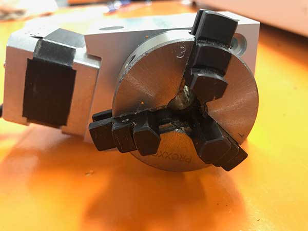
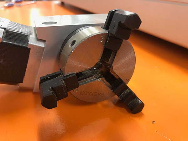
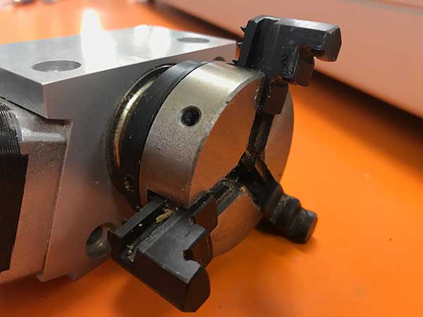
When you are machining circles on a CNC and your circles are not coming out perfectly round, it is commonly caused because there is some backlash developing on the machine. Backlash is a tiny amount of play that appears over time and is noticed when a drive changes direction. When running in a positive direction, the gears/lead screw are engaged with the lead screw nut on the gantry, but when the stepper motor reverses direction there is a tiny space between the lead screw and the lead screw nut that has to be made up before there is positive engagement in that direction. After many, many hours of use or if your machine is not properly maintained and lubricated, then this backlash can develop. If this is happening to you, please download this document: Stepcraft UCCNC Backlash Compensation. This will show you how to setup backlash compensation in UCCNC so that you can “dial” out any backlash and go back to having perfect circles again. The D-Series 420, 600 and 840 all have a max Z height of 140mm (5.51″). However this does not represent the maximum height of material you can process. From this height you need to subtract the spindle collet nut stick out as well as the length of the cutting tool you are using. The following represents the spindle and spindle nut stick out you get on a D-Series machine with the HF-500 and MM-1000 spindles HF-500: 31mm (1.22″) So if you take into consideration the MM-1000 with dual spacers, you would have a total Z height of 140mm (5.51″) minus 26.34mm (1.04″) leaving you with a new max Z height of 113.66mm (4.47″). Now depending on what you intend to do, you can use this new value to plan your project. If you want to cut all the way through material, you would need to have a tool that is long enough, which you would further subtract from the new Z height value. Example 1: New Z Value is 113.66mm (4.47″), if you divide that number in half, that would mean you can use a piece of material that is 56.83mm (2.23″) thick and the tool would have to stick out 56.83mm (2.23″) as well. Example 2: If you intend to only engrave on top of a piece of material, then your tool stick out can be much less. If you use an engraving blank that sticks out say 12mm from the bottom of the collet nut, then that means you can have a max material height of 101.66mm (4″). One way that you can increase your max material thickness that you can cut through is using double sided machining. Example: You can take your new Z value of 113.66mm (4.47″) and divide that into thirds. This would mean you can have a material thickness of 75.33mm (2.96″), or two-thirds and using a cutter with a length of 38mm (1.49″) you can cut one side of the project and then flip it over and cut the other side – so you are using a shorter cutter to cut through a thicker material by cutting each side. Example: STEPCRAFT CNC machines have two parameters in the specifications for their machines: Clamping Surface and Travel Distance Clamping Surface is maximum size of work material that you can place onto the machines bed. Travel Distance is the maximum amount that the gantry and cutting bit will move. As an example, the STEPCRAFT-2/300 has a clamping surface of 14.96″ x 8.74″ (380x222mm) but the travel distance is equal to 11.81″ x 8.27″ (300x210mm). This means that you can place a slightly larger workpiece onto the bed than you can actually cut. The number that is most important when choosing which size STEPCRAFT machine to buy is the Travel Distance. The following chart reflects these sizes as well as the overall dimension of the machines. Clamping Distance is the middle set of dimensions and Travel Distance is the Lower Set of Dimensions. The total travel distance for the Z axis is 5.5″. However, you need to keep in mind that some of that height will be used up by the systemheld tool that you place on the machine. For example, the HF500 spindle and collet stick below the tool holder by about 1.2″ This would reduce the total material height to 4.3″ From that you need to account for the length of the tool as well. A surfacing bit typically has a larger than normal cutting diameter (1 to 3 inches) and are used to flatten or level uneven surfaces on your project material. They are also used to take the thickness of a material down to a final required size. For example, you might have a piece of rough cut lumber that measures 1 inch in thickness but you need it to be 3/4 inch thick. If you don’t have a surface planer in your shop then you can use a surfacing bit with a pocket tool path to plane the material down. Another common use for surfacing bits is to clean up and level a spoil board. After continuous use your spoil board’s surface will have a lot of cuts in it and you might want to clean it up so it is perfectly smooth again. A surfacing bit is perfect for this, especially with machines where the spoil board is physically attached to the machine – you might want to prolong the use of it for as long as you can before replacing. Leveling your spoil board is also important. If you are looking to engrave .005″ into a piece of metal and your bed is off by a couple thousandths from one side to the other or front to back, then the thickness of your engraved lines will vary. By using a surfacing bit, you will ensure that your spoil board is perfectly level in relation to your gantry which will result in a uniform engraving. Note: Because of the larger diameter of a surfacing bit, it is important to note that you can not take as deep of passes or run as fast as you might with smaller end mills on most machines. Consult your machine’s manufacturer for assistance with proper speeds and feeds for surfacing bits. Yes you can remove the three tabs from the chuck and put them in the opposite way to allow for a larger opening for larger stock, up to 2 inches in diameter. To remove them, simply turn the inner ring behind the chuck counterclockwise and the threads will push the chuck tabs out. Then you can flip them around and while putting pressure on them turn the inner ring clockwise and they will be threaded back in. Many CNC machines will offer a dust boot or adapter that surrounds the spindle with a brush or rubber gasket material that rubs along the workpiece. A vacuum is connected to this adapter and dust is extracted right at the end mill. STEPCRAFT, for example, offers an exhaust adapter with a removable brush. To get the most out of your dust collection system you need to make sure that the brush is contacting the work surface. If not then only a percentage of the dust will be drawn into the dust collection system. Depending on the system you might need to use shorter bits to achieve this. To extract the dust you can use a simple shop vac or an integrated dust collection system. No, you do not need to use different spindles. The main factor will be how fast the feed rate will be that you run and how much material you remove per pass. If you with to run a light duty spindle like a Dremel 4000, you can run wood, plastics and metals just as well as if you were using a Kress 800W spindle. The only difference is that you will not be able to remove as much material and your feed rate will be slower the harder the material is. Keep in mind that dedicated CNC spindles will have better quality bearings which will offer less runout and therefore a longer life span and higher accuracy. Using the Dremel example, this device is not meant for hours and hours of prolonged use, nor is it made to have lots of pressure side loading the main shaft. You will find that if you are not careful on the feed rate and pass depth that you will quickly wear out the bearings. A router like the Dewalt DW611 will also cut all types of material, but as with the Dremel, the bearings are not as good as with a dedicated spindle so you can expect more runout with a router. The STEPCRAFT HF500 is a purpose built spindle that was designed to work with all types of materials and has an excellent bearing system that provides very little runout and a much higher accuracy. The bottom line is that you can pretty much cut whatever you like with just about any spindle. You just need to be cautious on feed rates and pass depth. Often times when cutting aluminum you will need a spoil board under the aluminum, especially when you are cutting all the way through the material. MDF is a very common material to use as a spoil board for the following reasons: Some things to be careful of when machining aluminum with an MDF spoil board: An alternative spoil board that we use is acrylic. Acrylic is hard, flat, easier to machine than aluminum so it will not strain your machine and if you want/need to use lubricant, then you can without worrying about it damaging the spoil board. Yes, you can use Vectric’s PhotoVCarve program, which allows you to create an engraving tool path for photos. Additionally, you can use the new Laser Engraving Head DL445 which can laser engrave your photos into a variety of materials.
Working With Woods
How come my circles are not perfectly round?

What is the total usable Z height on the D-Series CNC?
MM-1000: 38.6mm (1.52″)
MM-1000 (with single spacer): 32.56mm (1.28″)
MM-1000 (with dual spacers): 26.34mm (1.04″)
TWO SIDED MACHINING – For thicker material


What is the maximum height of the work material that I can place on the work bed?
What is a surfacing bit used for?

Is the chuck reversible on the 4th Axis unit?


Can I use MDF as a spoil board when cutting aluminum?
Can I engrave a photograph into a piece of wood?
Categories:
4th Axis,
Working With Woods
Categories:
Common Pre-Purchase Questions,
Working With Woods
